
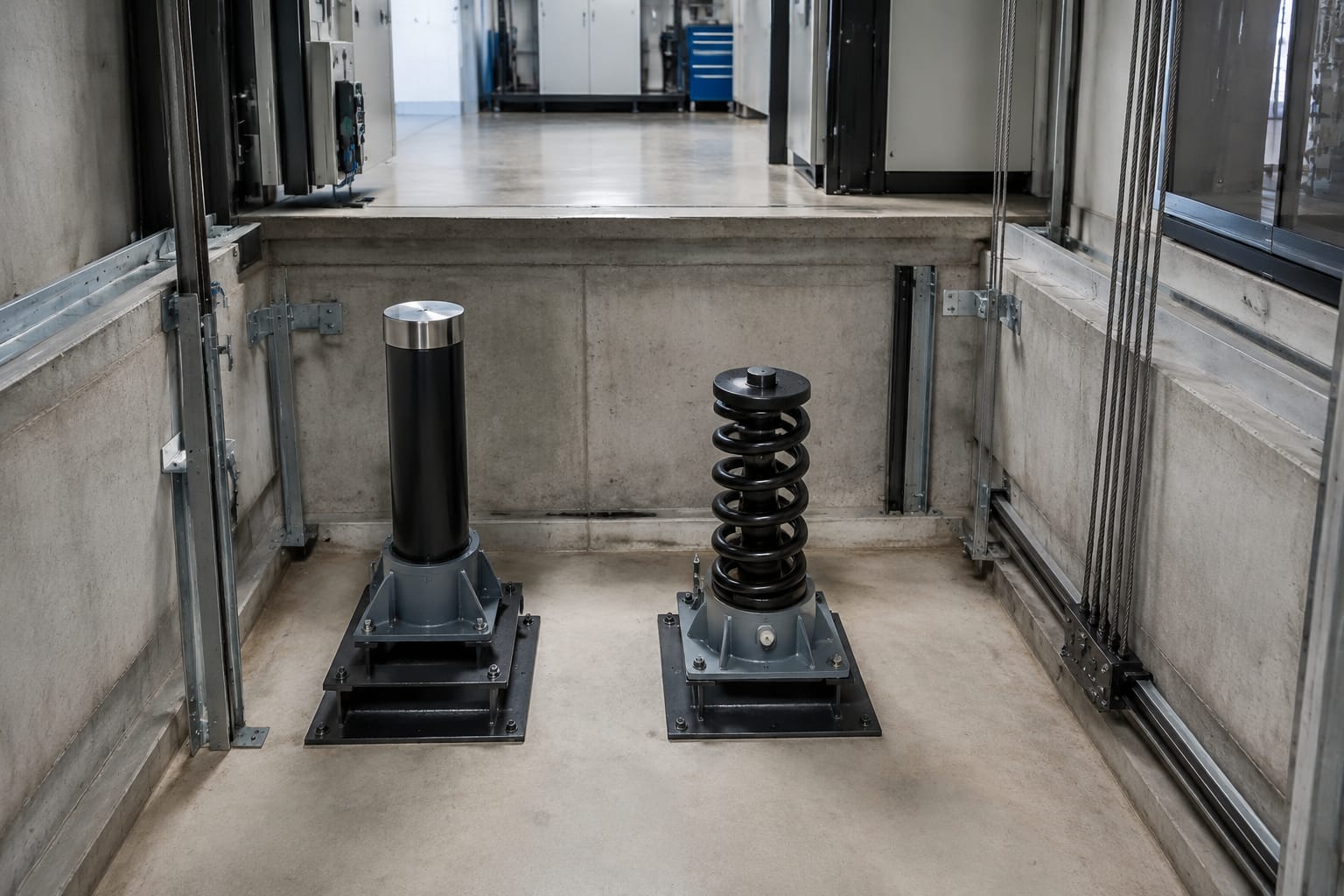
A buffer lift system is the final energy-absorbing safeguard at the bottom of an elevator shaft. It supports the car or counterweight only if it travels beyond its normal lowest position, reducing the consequences of an overtravel event. Correct selection depends on the equipment's rated speed, moving mass, available pit space, buffer stroke and the applicable lift code.
For maintenance and procurement teams, a buffer is not a generic pit component. A replacement must match the original duty and physical installation, while its switch arrangement and electrical proving must work correctly with the safety circuit. Never select a buffer solely by its outside diameter or apparent similarity.
What an elevator buffer does
Elevator buffers are mounted in the lift pit beneath the car, the counterweight, or both, depending on the lift arrangement. During normal operation, the car and counterweight do not rest on them. They act only when a descending component reaches the end of permitted travel.
A correctly specified buffer performs three related functions:
- It absorbs or stores the kinetic energy of the moving car or counterweight during overtravel.
- It limits deceleration to the level expected by the lift design and applicable requirements.
- It provides a stable, correctly positioned stop at the bottom of travel.
Buffers are part of a wider protection system. They do not replace correct terminal stopping, levelling, overspeed governor operation, limit switches or maintenance of the lift controller. If a buffer has been struck, treat it as evidence of an abnormal event and investigate the cause before returning the lift to service.
Common causes that can lead to buffer contact include failed or incorrectly adjusted terminal limits, loss of traction, control faults, brake issues, setup errors during servicing, and unintended movement during inspection. The root cause matters as much as restoring the buffer itself.
Oil buffers versus spring buffers
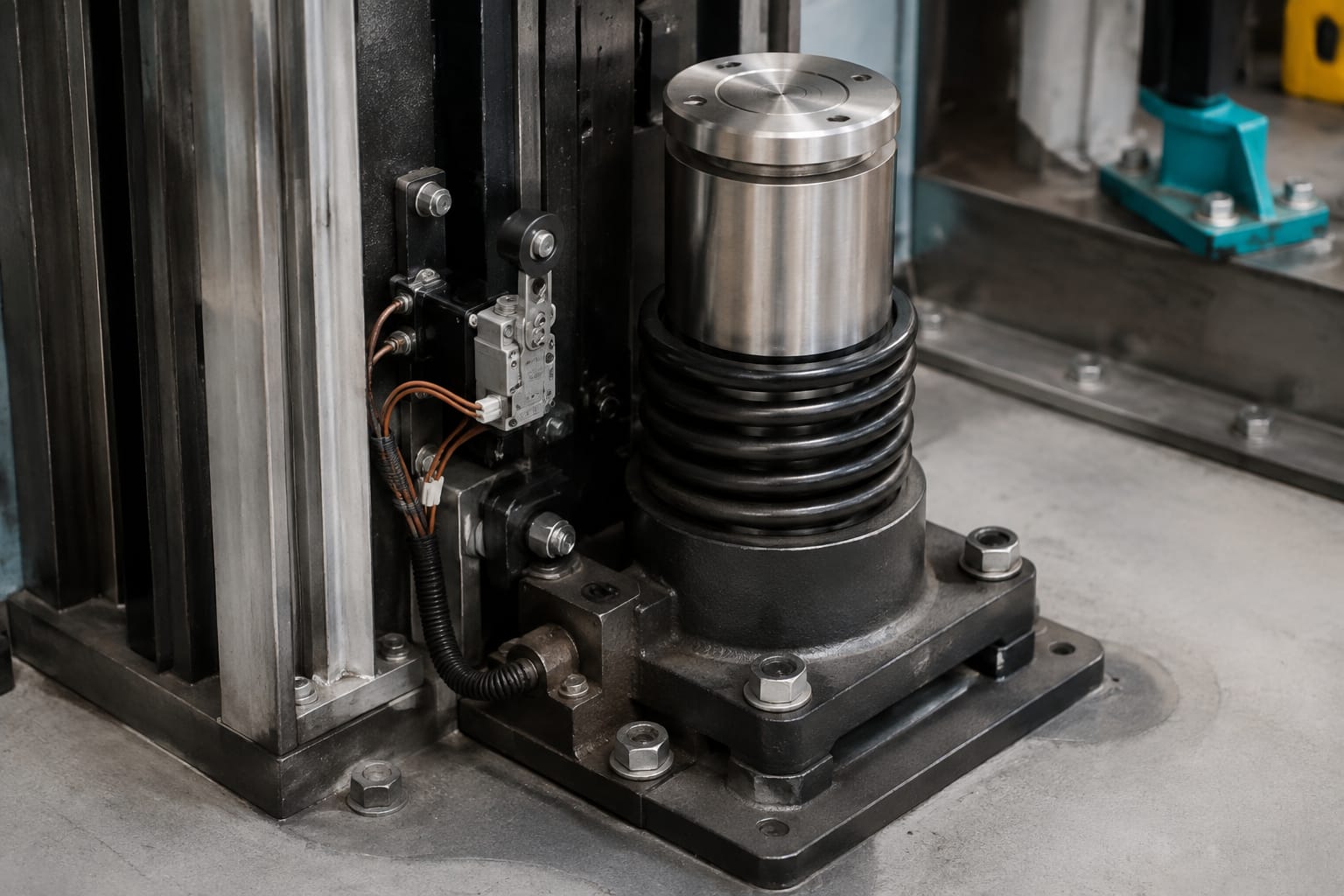
The two broad buffer lift categories are spring buffers and oil buffers, often called hydraulic buffers. Both protect the car and counterweight at the bottom of the shaft, but they manage energy differently and are suitable for different applications.
| Feature | Spring buffer | Oil buffer |
|---|---|---|
| Energy control | Compresses a spring to store energy | Forces oil through controlled hydraulic passages to dissipate energy |
| Typical use | Lower-speed lift applications, subject to design and applicable code | Higher-speed applications or duties requiring controlled deceleration |
| Return behaviour | Spring returns after compression | Plunger must return fully; some designs include a reset or return arrangement |
| Main inspection focus | Spring condition, compression, seating, corrosion and alignment | Oil leakage, plunger condition, fluid level, return position, corrosion and switch operation |
| Important limitation | Stored spring energy can cause rebound characteristics | Leakage, low oil level or a plunger that does not reset can impair performance |
Spring buffers
A spring buffer uses one or more heavy-duty springs inside a housing. On impact, the spring compresses and absorbs kinetic energy. Its construction may appear simple, but it still needs careful matching to travel, load and impact conditions.
Spring buffers can be appropriate where the lift's rated speed and design permit their use. They require enough available compression travel and must remain upright, secure and free from substantial corrosion. A weakened, broken, permanently set or incorrectly seated spring is not acceptable.
A key limitation is that a spring stores energy rather than dissipating it in the same controlled manner as an oil buffer. This is why the permitted application is closely linked to lift speed and the governing requirements. Do not substitute an oil buffer with a spring type, or vice versa, merely because the mounting dimensions can be adapted.
Oil buffers
An oil buffer uses a piston or plunger moving through hydraulic oil. Restriction of oil flow creates resistance over the stroke, allowing the impact energy to be dissipated in a controlled way. These buffers are commonly specified where a longer, more controlled stopping action is required.
Oil buffers demand more detailed servicing. The oil level, grade, seals, plunger surface, cylinder condition and return position all matter. A unit with oil around its base may have a seal fault, damaged cylinder, loose plug, overfill, or residue from prior servicing. The source must be identified rather than assuming it is harmless.
Where a replacement is required, compare the complete approved product data and original lifting documentation. A visually similar hydraulic unit may have a different stroke, damping characteristic, rated capacity or switch configuration.
For component sourcing, maintenance teams can compare the physical details against [hydraulic oil pressure buffer lift parts and elevator accessories](/products/hydraulic-oil-pressure-buffer-lift-parts-elevator-accessories/) only after establishing the required technical duty from the existing lift documentation.
Car and counterweight applications
Most traction lifts require buffers below both the car and the counterweight because either component can reach the pit during abnormal travel. The exact number, layout and working position depend on the lift's roping arrangement, car frame, counterweight frame and pit design.
The car buffers must align with the car frame's striking plate or buffer contact surface. Counterweight buffers must align with the counterweight frame. Misalignment can cause side loading, damage a plunger, bend a striking plate or prevent the buffer from compressing along its intended axis.
When checking either application, confirm:
- The buffer centreline matches the respective striking surface.
- The striking plate is flat, secure and not bent or cracked.
- The specified clearance and working position are maintained at normal bottom landing conditions.
- The pit floor, buffer pedestal and fixings are sound.
- No pit equipment, cable, debris or temporary material can obstruct full buffer travel.
- The car and counterweight have the required clearances at their extreme positions.
Do not assume the car-side and counterweight-side buffer are interchangeable. Even where they look identical, a lift may use different duties because the masses, striking arrangements or specified operating conditions differ.
Stroke, speed and load considerations
Buffer selection starts with the lift's actual rated conditions, not an estimate. The required buffer must manage the energy associated with the component that may strike it, within the permitted stroke and deceleration characteristics of the lift design.
The main data to verify are:
- Rated speed of the lift.
- Whether the buffer protects the car, counterweight or both.
- Car mass, rated load and any relevant balancing information.
- Original buffer make, model, part number and type.
- Rated load or capacity marked on the buffer, where provided.
- Usable stroke and fully compressed height.
- Overall height at normal position.
- Base mounting pattern, bolt size and pedestal dimensions.
- Striking plate diameter, position and alignment.
- Pit depth and specified safety clearances.
- Applicable code, original approval documentation and site requirements.
Why stroke cannot be guessed
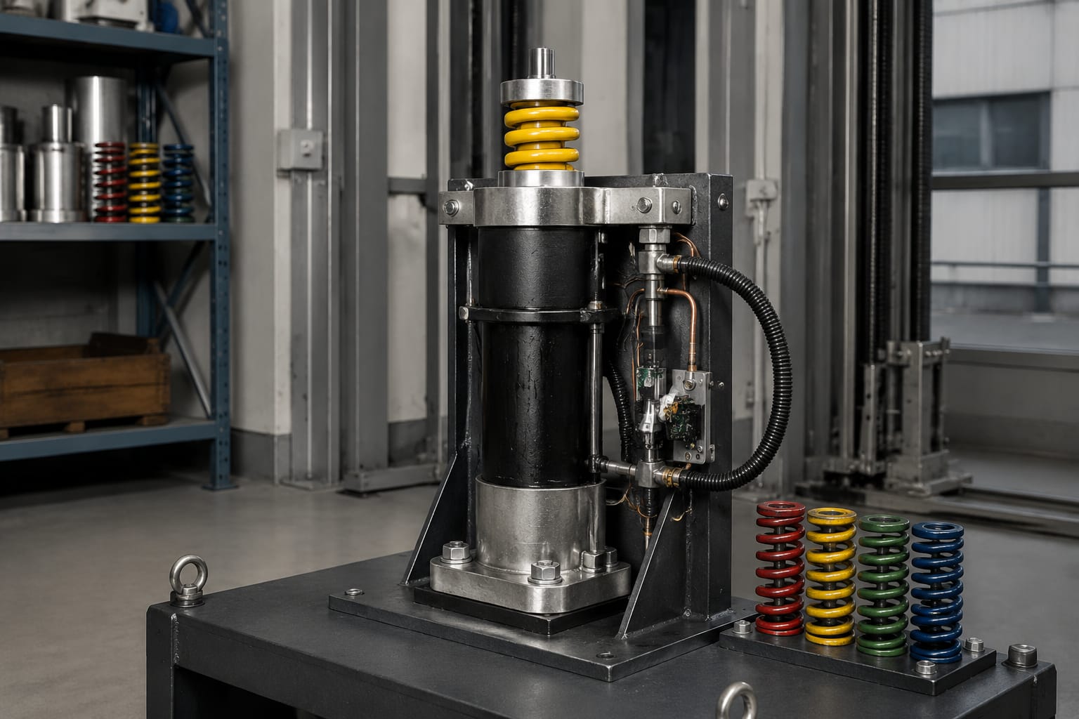
Stroke is the distance over which a buffer can absorb energy. A shorter buffer may physically fit but stop the moving mass too abruptly, while an overlong unit may affect required pit clearances or fail to match the intended striking position.
For an oil buffer, the plunger's effective working stroke and damping arrangement are critical. For a spring buffer, the available spring compression and final solid height are critical. Overall housing height alone is not a reliable indication of either value.
Take measurements with the lift safely isolated, supported and under the site’s approved maintenance procedure. Measure from fixed reference points, record the buffer's normal extended position, and note whether the plunger is fully returned before comparing dimensions.
Speed and load are linked
A heavier moving mass or higher speed increases the energy that must be managed. That is why a buffer label may state a capacity range, speed-related designation or product reference rather than just a physical size.
Do not use a buffer from another lift simply because it has the same base plate. Modernisation work can alter car mass, rated load, drive behaviour or counterweight arrangement. Review the lift design documentation whenever major components have changed, including car refurbishment, sling changes, load upgrades or drive replacement.
Applicable Indian codes, project specifications and authority requirements may determine the permitted buffer type, installation and test method. The lift manufacturer’s documentation and the competent person responsible for the installation should govern where requirements differ.
Buffer switches and electrical proving
Many oil buffers incorporate a switch that indicates whether the plunger has returned to its normal extended position after operation. This is often called a buffer switch, reset switch or electrical proving switch. Its purpose is to prevent normal operation while the buffer remains compressed or has not reset correctly.
The controller safety circuit must receive the intended state only when the buffer is in its correct normal position. If an oil buffer does not return fully, the lift may remain out of service until the underlying mechanical or hydraulic issue is resolved. Bypassing the circuit to move the lift is unsafe and can conceal a serious fault.
Spring buffer arrangements may also have position monitoring depending on the lift design. Always check the original electrical drawings rather than assuming every buffer requires the same switch or contact logic.
When replacing a switch, verify:
- Correct switch type and contact arrangement.
- Required normal state and circuit function.
- Actuator or lever geometry at full buffer extension.
- Mounting position and cable routing.
- Protection against oil, water, impact and cable damage.
- Continuity through the controller safety circuit.
- Mechanical operation throughout the relevant buffer travel.
A compatible physical switch is not necessarily electrically compatible. The contact configuration, actuator travel, mounting bracket and cable entry can all differ. Product-specific [elevator buffer switch parts](/products/3300-3600-elevator-buffer-switch-parts-lift-parts/) should be checked against the original part reference and circuit requirements. Where the installation uses that manufacturer-specific arrangement, confirm compatibility with the relevant [Mitsubishi lift buffer switch part](/products/elevator-buffer-switch-mitsubishi-lift-parts/) rather than relying on appearance.
Leakage, corrosion and damage checks
Routine pit inspections should include a close visual and functional check of every buffer. Poor lighting and accumulated pit debris can hide defects, so clean the immediate inspection area before assessing the component.
Oil-buffer inspection checklist
For an oil buffer, look for:
- Oil leakage from seals, plugs, joints or the base.
- A plunger that is not fully extended in the normal position.
- Scoring, pitting, rust or deposits on the plunger rod.
- Dents, cracks or corrosion on the cylinder and base.
- Missing, loose or damaged fasteners.
- Incorrect oil level or unsuitable fluid, where the manufacturer's procedure permits checking.
- Damaged switch bracket, actuator, conduit or cable.
- A buffer that is leaning or has shifted on its pedestal.
- Evidence of previous impact, including distorted striking plates.
Do not top up oil without first identifying the approved fluid and the source of loss. Mixing oils or filling above the specified level can affect buffer performance. A heavily corroded plunger surface can damage seals and lead to recurrent leakage even after a temporary repair.
Spring-buffer inspection checklist
For a spring buffer, inspect for:
- Broken, cracked, distorted or permanently compressed springs.
- Corrosion between coils or at spring seats.
- Damaged guide rods, housings or retaining hardware.
- Spring movement that is not concentric with the housing.
- Loose base bolts or a damaged pedestal.
- Cracked welds, worn striking surfaces or tilted installation.
- Foreign material restricting compression or return.
Any deformation, substantial corrosion, missing component or evidence of impact requires further assessment. Do not paint over corrosion as a corrective action. Surface treatment may be appropriate only after the competent person has determined that the base material and dimensions remain acceptable.
Replacement identification and installation
A reliable replacement decision begins with a complete identification record. Photograph the buffer from all sides, including nameplates, labels, base plate, switch, plunger and striking plate. Record measurements in millimetres and note whether the buffer is installed beneath the car or counterweight.
Use the following sequence.
- Isolate the lift and secure the car or counterweight under an approved maintenance procedure. Do not work beneath an unsupported suspended load.
- Record the original buffer manufacturer, model, serial or part number, type, marked rating and date information where present.
- Obtain the lift's rated speed, car mass, rated load, counterweight details and original drawings or maintenance documents.
- Measure extended height, compressed height where documented, stroke, base footprint, fixing centres and striking interface.
- Verify switch type, contact function, connector or cable arrangement, and safety-circuit wiring.
- Check the pit pedestal and striking plate before ordering. A replacement buffer cannot correct structural damage or incorrect geometry.
- Select an equivalent approved unit based on technical data, not an approximate visual match.
- Install using the specified fixings, torque values, alignment method and fluid procedure supplied for that equipment.
- Restore all guards, wiring protection and pit housekeeping before functional checks.
Common replacement mistakes include reusing corroded fasteners, fitting a buffer with the wrong extended height, ignoring a non-returning oil plunger, using an unverified oil grade, and transferring a switch without checking its actuation point. Another frequent error is replacing a damaged buffer before investigating why it was contacted.
Kelevator supplies multi-brand elevator spare parts for B2B importers, distributors, maintenance contractors and OEM buyers. For procurement, provide the recorded identification data and lift duty information so the proposed part can be assessed against the actual requirement.
Post-service inspection and testing
After installation, repair or suspected buffer contact, inspect the complete arrangement before the lift is returned to normal use. The exact test procedure must follow the applicable code, manufacturer instructions, site risk assessment and competent-person requirements.
At minimum, post-service checks should confirm:
- The correct buffer type and documented duty have been installed.
- Base bolts, brackets and pedestal connections are secure.
- The buffer is vertical and aligned with its striking plate.
- Required clearance, extended height and usable travel are present.
- Oil-buffer plungers are fully returned and free from leakage.
- Buffer switches actuate at the intended position.
- The safety circuit prevents operation when the monitored buffer is not in its normal position.
- Cables, conduits and switch guards cannot foul moving parts.
- The pit is clear and all temporary tools or supports are removed.
- The cause of any earlier buffer contact has been investigated and corrected.
A functional test should never be improvised by deliberately driving a car into the buffers. Any dynamic or overspeed-related testing needs the prescribed method, suitable equipment and competent supervision. Record the inspection findings, part identification, measurements, switch test result, corrective work and release decision in the maintenance records.
FAQ
Can a spring buffer replace an oil buffer?
Not as a like-for-like assumption. Buffer type is linked to speed, energy absorption, stroke, lift design and applicable requirements. Use the original technical documentation and a competent engineering review before changing type.
Is a small oil leak from a buffer acceptable?
It should be investigated. Oil loss can indicate a deteriorating seal, damaged plunger or another fault that may affect performance. Confirm the source, fluid condition and return operation before deciding whether repair or replacement is required.
What information is needed to identify a replacement buffer lift part?
Collect the original part number, buffer type, rated lift speed, protected component, marked rating, extended height, stroke, base fixing dimensions, striking plate details and switch configuration. Clear photographs of labels and the installation are also useful.
Why will a lift not run after a buffer has compressed?
An oil buffer may not have returned to its normal position, so its proving switch can keep the safety circuit open. The lift should remain out of service until the buffer has been inspected, reset as specified and the cause of the event has been corrected.
For a practical replacement enquiry, start with the buffer identification record, lift rating data and clear site measurements. This allows the buffer, switch and mounting arrangement to be checked as a complete safety-critical assembly.