
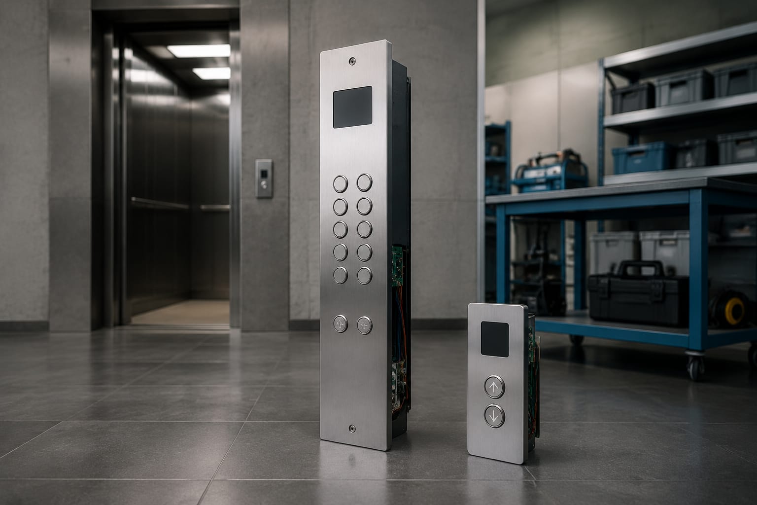
An elevator button panel is the operating interface that lets passengers call a lift, select a floor, open or close doors, and use emergency functions. The two main panel types are the car operating panel (COP) inside the lift car and the landing operating panel (LOP) outside the lift at each floor.
For maintenance and replacement work, appearance alone is not enough. A suitable elevator button panel must match the controller logic, electrical ratings, connector type, cable pinout, mounting dimensions, display arrangement and safety functions of the existing installation. This guide explains what to inspect before sourcing a replacement or planning a lift modernisation.
COP and LOP explained
A COP and LOP perform different functions and are usually connected to different controller inputs, even when their buttons look similar.
| Feature | COP: Car Operating Panel | LOP: Landing Operating Panel |
|---|---|---|
| Location | Inside the elevator car | At lift landings |
| Main purpose | Lets passengers choose a destination and operate car functions | Lets passengers register an up or down call |
| Typical controls | Floor buttons, door open, door close, alarm, emergency call, fan or light controls | Up/down call buttons, directional arrows, position indicator |
| Floor identification | Usually includes a full set of served floors | Usually displays the current floor or travel direction |
| Wiring considerations | Often has more signals and may connect through a travelling cable | Usually connects through landing wiring to the controller |
| Replacement priority | Passenger operation, accessibility, emergency controls, car aesthetics | Call reliability, traffic flow, vandal resistance and landing finish |
Car operating panel: COP
The COP is the main control surface within the lift car. In a standard passenger elevator, it commonly includes floor-selection buttons, door open and door close buttons, an alarm button and a display showing floor position or direction of travel.
Depending on the lift type, a COP may also include:
- Emergency telephone or intercom provision
- Fire service or attendant controls where applicable
- Keyswitches for authorised operation
- Fan and light switches
- Overload indicator
- Card reader or access-control interface
- Braille or raised floor markings
- Voice-announcement speaker grille
A COP must be designed around the actual floors served. For example, a building with basement parking, a podium level and upper residential floors needs an accurate button layout, labels and controller programming. Simply fitting a panel with unused or incorrectly labelled buttons can confuse passengers and complicate maintenance.
Landing operating panel: LOP
An LOP is installed at a landing, generally next to the lift entrance. Its primary function is to send an up or down call to the elevator controller. A single-button LOP is common at terminal floors where travel is possible in one direction only. Intermediate floors generally use separate up and down buttons.
LOPs can be simple push-button stations or integrated units with direction arrows, floor-position displays, access-control readers and destination-control functions. In busy commercial buildings, clear visual feedback is important: passengers should be able to see that a call has registered and which direction the arriving car will travel.
For installations that use an integrated visual call interface, assess whether an outbound call LCD panel system is compatible with the controller and the building’s intended traffic arrangement before specifying it.
Parts inside an elevator button panel

A complete elevator button panel is an assembly, not just a stainless-steel plate with switches. Understanding its individual parts helps identify whether a fault can be repaired at component level or requires a full panel replacement.
Faceplate and mounting frame
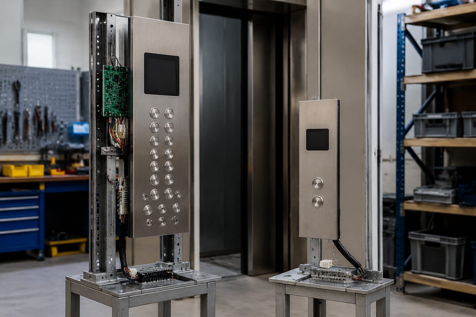
The faceplate is the visible front surface that holds buttons, displays, labels and openings. Behind it may be a mounting frame, back box or support bracket. These components determine how the panel fits into the car wall or landing jamb.
Before replacing a faceplate, record its height, width, thickness, corner treatment, fixing-hole positions, cut-out dimensions and rear clearance. A panel that matches the visible dimensions may still fail to fit if the rear box is too deep or the fixing studs are in different positions.
Push buttons and indicator lamps
Lift buttons commonly include a mechanical actuator, lamp or LED illumination, bezel, contact assembly and wiring terminals. Button feedback can be provided through a halo, face illumination, dot indicator or separate acknowledgement lamp.
Confirm the following before ordering button replacements:
- Button shape and diameter or square dimensions
- Flush, raised or projecting profile
- Illumination voltage and LED polarity, where relevant
- Contact arrangement, such as normally open or normally closed
- Terminal, plug or board-mounted connection
- Engraving, symbol, floor designation and language requirements
- Colour and brightness of registered-call indication
Do not assume all round buttons are interchangeable. Their retaining method, travel, illumination circuit and controller input arrangement may differ.
Position indicators and displays
A display may show the car’s current floor, travel direction, overload status, fire service mode or fault condition. Older installations may have seven-segment displays, while newer panels may use dot-matrix, LCD or TFT display modules.
When assessing a display replacement, check:
- Display technology and physical viewing area
- Character colour and background contrast
- Supply voltage
- Data protocol or signal method
- Mounting cut-out and display orientation
- Compatibility with the controller’s serial communication or discrete outputs
A display can appear physically suitable but remain blank if it expects a different communication protocol from the elevator controller.
Control board and button board
Many modern panels use a PCB or button board to consolidate inputs, LED outputs and communications. The board may be dedicated to the COP, the LOP, a display module or a particular controller family.
A board failure should be diagnosed carefully. Check for loose connectors, damaged tracks, moisture ingress, failed LEDs, corroded terminals and supply-voltage faults before declaring the PCB defective. Where a replacement is necessary, use board identifiers, connector references, revision numbers and wiring documentation rather than relying only on the panel’s outside appearance.
For component-level sourcing, review the specifications of an elevator control panel button board and lift accessories against the existing board and system documentation.
Wiring harnesses, cables and connectors
Panel wiring joins buttons, displays, boards, keyswitches and emergency devices to the lift controller. In the car, COP signals may pass through the travelling cable. At landings, LOP wiring generally runs through the hoistway installation.
Common connection arrangements include screw terminals, crimp terminals, ribbon cables, multi-pin plugs and serial-bus connectors. The pin count alone does not establish compatibility. A 10-pin cable can have different wire assignments, shielding, conductor size, keying and electrical roles.
Button and display configurations
The right configuration depends on building use, lift capacity, controller capability and passenger needs. It should be planned around actual operation rather than the number of unused openings on a standard panel.
Typical COP configurations
A basic passenger COP may include all floor buttons, door open, door close and alarm. More complex configurations may add:
- Basement, parking and service-floor buttons
- Restricted-floor keyswitch or card access
- Separate emergency communication button
- Firefighter or attendant controls as required by the installation
- Digital floor display and direction arrows
- Overload and no-smoking indicators
- Audio announcement interface
- Braille markings and tactile symbols
Floor buttons should be ordered logically, normally from lower to higher floors. Where there are many stops, a dual-column layout can reduce panel length and improve reachability. However, the spacing, button grouping and marking method should remain easy to understand for first-time users.
Typical LOP configurations
A conventional LOP has one or two call buttons. The basic rule is straightforward:
- Use one call button at a top or bottom terminal landing.
- Use up and down call buttons at floors where passengers can travel in either direction.
A higher-specification LOP can incorporate a floor indicator, direction arrows, a hall lantern, access reader or LCD interface. In a group-controlled system, the landing display and call-registration behaviour must be matched to the controller logic. A visual panel from another system may not provide correct direction or arrival information.
Avoid over-specifying controls
Adding a feature is only useful when the controller can support it and the building needs it. A card reader requires a working access-control design. A destination-style screen requires compatible group-control logic. An extra display needs the correct data signal.
For a modernisation project, distinguish between:
- A cosmetic panel upgrade using existing signals.
- A functional upgrade that changes buttons, indicators or access operation.
- A controller modernisation that enables new panel functions.
This prevents a visually upgraded panel from being expected to deliver features the existing controller cannot provide.
Faceplate materials and dimensions
Faceplate choice affects durability, cleaning, perceived quality and installation practicality. In India, panels in high-traffic residential towers, hospitals, retail premises and public-facing buildings may face frequent cleaning, humidity, abrasive use and occasional impact.
Common faceplate materials
Stainless steel is widely used because it is durable and suits many lift interiors. Hairline, brushed, mirror and patterned finishes create different visual effects, but mirror finishes show fingerprints and scratches more readily.
Powder-coated mild steel can be suitable for certain applications and offers colour flexibility. The coating quality, edge finish and corrosion environment should be considered.
Acrylic, polycarbonate or glass overlays may be used for displays, printed graphics or specialist designs. These should be selected with attention to scratch resistance, impact performance and availability of replacement parts.
Bronze-tone, titanium-tone or decorative metal finishes may support an architectural interior, but replacement matching can be harder if a special finish is discontinued.
Measurements to capture before ordering
Provide complete dimensional information, preferably with clear photographs and a measured drawing:
- Overall faceplate height and width
- Thickness of plate and rear assembly
- Cut-out sizes for buttons and displays
- Centre-to-centre spacing between buttons
- Screw holes, studs, clips or bracket locations
- Depth available inside the wall or car return panel
- Position of cable entry and connector clearance
- Engraved floor sequence and symbols
Measure in millimetres and avoid estimating from photographs. A few millimetres of difference can prevent correct installation or leave visible gaps around the panel.
Board, cable, and connector matching
Electrical compatibility is the most important replacement check. A panel can have the right dimensions and still be unsuitable if its board, cable or connector does not match the existing elevator system.
What to verify
Start with the controller make and model, then record the part number and revision code printed on the existing panel board. Photograph both sides of the board where possible, including connector labels and cable colours.
Confirm:
- Controller make, model and software or board family where known
- Existing board part number and revision
- Supply voltage and polarity
- Number of buttons, indicators and auxiliary devices
- Connector type, keying and number of pins
- Pinout or wiring diagram
- Communication method, such as discrete wiring, serial bus or CAN-based arrangement
- Cable length, conductor count and shielding requirements
- Input and output function for each connection
For example, a multi-core panel cable must match the exact connector orientation and pin allocation. A replacement 10-pin COP/LOP connection cable should be compared against the original cable’s part reference, pinout, connector key and intended application before installation.
Common compatibility mistakes
The following errors can lead to non-functioning buttons, damaged electronics or avoidable rework:
- Ordering by panel size or photo only
- Treating the same pin count as proof of the same wiring
- Ignoring board revision codes
- Reusing a damaged harness with a new panel
- Swapping LED polarity or supply-voltage requirements
- Omitting the display communication check
- Failing to label wires before disconnecting an older panel
- Assuming floor labels correspond to controller input order
Where documentation is unavailable, retain the removed panel, connectors and cable assembly until the replacement has been tested and accepted.
Accessibility and emergency controls
Elevator controls should be usable by a broad range of passengers and should support safe response in an emergency. The exact requirements depend on the building type, equipment design and applicable project specifications, so verify the relevant statutory, code and consultant requirements for the installation.
Accessible panel features
Useful accessibility considerations include:
- Tactile floor markings and Braille identification
- Raised symbols for door open, door close and alarm functions
- Adequate contrast between buttons, markings and faceplate
- Clear registered-call illumination
- Sensible mounting height and reach range
- Audible floor information or voice-announcement compatibility
- Large, legible floor indicators
- Distinctive placement of emergency controls
Avoid treating Braille dots as a decorative feature. They must correspond accurately to the floor designation and be positioned consistently with the button layout.
Emergency functions
The alarm button, emergency communication provision and any required emergency operation controls must remain identifiable and operational after panel work. During replacement, check that emergency devices have not been disconnected, blocked by the faceplate or confused with normal passenger controls.
Do not alter firefighter, attendant, inspection or other restricted operational controls without the correct system knowledge and project authorisation. These functions can involve controller-specific wiring and building safety procedures.
Customization and modernization options
An elevator button panel modernisation can improve usability and refresh the car or landing appearance without necessarily replacing the full lift system. The viable scope depends on the existing controller, wiring condition, car interior and building requirements.
Cosmetic upgrades
A cosmetic upgrade may include a new stainless-steel faceplate, updated button finish, clearer floor labels, replacement display lens or revised engraving. This approach is suitable when the existing electronics and wiring remain reliable and compatible.
Confirm whether the new faceplate can reuse the existing buttons and display modules. Changes to cut-outs, button depth or mounting points may turn a cosmetic job into a broader electrical modification.
Functional upgrades
Functional changes can include illuminated buttons, revised displays, added hall lanterns, access-control provision, voice-announcement interfaces or updated emergency communication cut-outs. These may require additional wiring, controller inputs or replacement boards.
Before approving a functional upgrade, establish which features are supported by the present controller and which require controller changes. A maintenance contractor should also consider whether replacement modules will remain available for the intended service life.
Custom panel planning
For custom COPs and LOPs, prepare a specification covering:
- Building nameplate or branding requirements, if any
- Faceplate material and finish
- Exact floor list and button arrangement
- Language, engraving and tactile marking requirements
- Display type, colour and location
- Access-control or keyswitch functions
- Controller and connector details
- Installation dimensions and rear depth
- Quantity required, including spare modules where appropriate
Kelevator supplies multi-brand elevator spare parts for B2B importers, distributors, maintenance contractors and OEM buyers. For custom or replacement panel sourcing, a complete technical record reduces the risk of receiving a visually similar but electrically incompatible assembly.
Panel testing and commissioning
A new or repaired elevator button panel should be tested as part of the lift system, not only checked on a workbench. Testing should be carried out by competent personnel using site-safe procedures and in coordination with the elevator controller work.
Pre-power checks
Before energising the panel:
- Compare every connector with the approved wiring diagram or recorded original connection.
- Check that no wires are pinched behind the faceplate.
- Confirm correct earth bonding where provided.
- Inspect terminals for loose screws, damaged crimping or exposed conductors.
- Verify connector keying and orientation.
- Check that the panel is securely mounted and edges are not sharp.
Functional checks
After power is restored, test each function methodically:
- Every COP floor button registers and sends the car to the correct floor.
- Door open and door close functions operate correctly where fitted.
- Each LOP call button registers the intended direction.
- Button illumination and call acknowledgement are visible.
- Position indicators show the correct floor and direction.
- Emergency alarm and communication-related functions are checked according to site procedure.
- Access controls, keyswitches and restricted floors behave as intended.
- Displays, buzzers and voice interfaces work without intermittent faults.
- The panel remains stable during normal car movement and door operation.
Record any changes to wire numbering, board revisions, panel layout and floor labels in the maintenance file. This makes the next repair faster and avoids uncertainty when a different technician attends the site.
FAQ
Can a COP be used in place of an LOP?
No. A COP and LOP have different operating functions, button arrangements and controller connections. Some product families share similar styling, but their internal board and wiring requirements may still differ.
Is a same-size elevator button panel a direct replacement?
Not necessarily. Match the mounting details, button cut-outs, board reference, supply, connector type, pinout and controller communication before treating it as a direct replacement.
Should a faulty panel always be replaced completely?
No. A single button, lamp, display module, connector or harness may be repairable. Full replacement is more appropriate where the faceplate is damaged, multiple components are unreliable, parts are obsolete or a modernisation is planned.
What information should be sent when requesting a replacement panel?
Send clear front and rear photographs, dimensions in millimetres, controller make and model, board and cable part numbers, connector photographs, wiring details, required floor labels and the number of panels needed.
For replacement planning, begin by documenting the existing COP or LOP before removing it. Matching the electrical interface alongside the panel dimensions will produce a more reliable result than selecting an elevator button panel by appearance alone.
Related product references
For practical catalog examples related to this topic, review [Elevator Control Panel Button Board lift accessories](/products/elevator-control-panel-button-board-lift-accessories/), [3300 3600 5500 LOP COP Control Panel Connection Cable 10 Pin Core lift accessories](/products/3300-3600-5500-lop-cop-control-panel-connection-cable-10-pin-core-lift-accessories/), and [Outbound call LCD panel STEP system elevator parts](/products/outbound-call-lcd-panel-step-system-elevator-parts/). Confirm the exact model, dimensions, ratings, and connectors before ordering.