
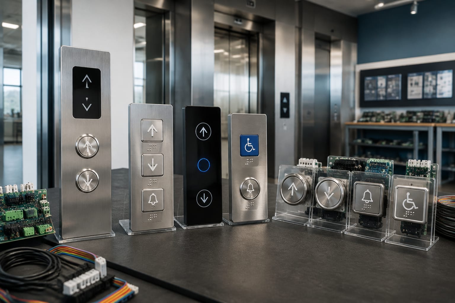
Elevator buttons are the user-facing controls that send floor, direction, door and emergency commands to a lift system. For reliable operation, a replacement button must match more than its visible size: the mounting method, contact arrangement, illumination supply, controller interface, legend and tactile markings all matter.
For maintenance contractors and sourcing teams, the practical distinction is between car operating panel (COP) buttons inside the lift and landing call buttons outside it. Both may look similar, but they often have different symbols, circuit behaviour and board compatibility. Selecting by photograph or colour alone is a common cause of repeat failures and unsuitable installations.
Car operating and landing call buttons
Car operating buttons are installed within the lift car, normally on the car operating panel. They allow passengers to select floors and use functions such as door open, door close, alarm and emergency communication. In some systems, the COP also includes key-switch functions, service controls or access-controlled floor selection.
Landing call buttons are installed at each floor outside the lift. Their task is simpler: they register a passenger's intended travel direction and send the call to the control system. A typical intermediate landing has separate up and down buttons, while the top floor normally requires only down and the lowest floor normally requires only up.
| Control location | Typical buttons | Main purpose | Common sourcing check |
|---|---|---|---|
| Car operating panel | Floor numbers, door open/close, alarm, emergency call | Select destination and operate car functions | Button cut-out, legend, lamp/LED voltage, terminal configuration |
| Landing operating panel | Up and down arrows | Register travel direction | Single or dual button arrangement, arrow direction, back-box or fascia fit |
| Fire/service panel | Key switch, designated controls | Enable authorised operational modes | Controller-specific wiring and keying requirements |
| Destination control terminal | Keypad, touchscreen or floor selection buttons | Register destination before entering the car | Proprietary protocol, display module and software compatibility |
A car button normally records a destination request. A landing button requests a direction, not a particular car or floor. In a group installation, the controller decides which car should answer the landing call. This is why a landing-call button cannot generally substitute for a floor-selection button even if the physical actuator appears identical.
The panel location also affects the operating environment. Car buttons are exposed to frequent hand contact, cleaning chemicals, trolley impact and occasional misuse. Landing buttons may face dust, moisture or temperature variation depending on the building entrance and enclosure. The bezel material, ingress protection design, fixing method and panel finish should suit the installation conditions.
Common elevator button symbols
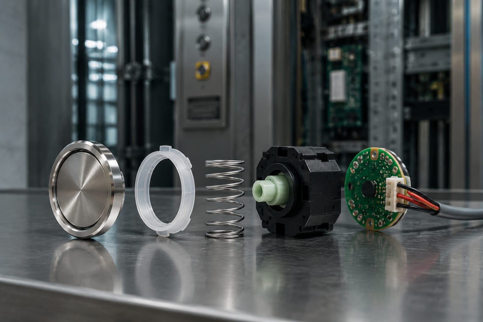
Symbols make elevator controls usable across language groups and help passengers recognise urgent or routine functions quickly. The graphic must be correctly printed, etched, moulded or illuminated, and it must match the intended controller function.
The most common elevator button symbols include:
- Floor number or letter: Selects the marked floor. Basement levels may be shown as B1, B2 and so on; building conventions differ, so match the existing site identification.
- Up arrow: Places an upward landing call.
- Down arrow: Places a downward landing call.
- Two arrows pointing apart: Door open. It requests the doors to remain open or reopen, subject to controller logic.
- Two arrows pointing together: Door close. It requests door closing, but safety sensors and controller timing can override it.
- Bell symbol: Alarm. It activates the alarm circuit or sends an alarm command, depending on the system.
- Telephone or communication symbol: Emergency communication, where fitted. This must not be assumed to be the same as the alarm function.
- Star or raised marking: Identifies the main exit level in many installations. The exact convention and local requirements should be checked for the project.
- Firefighter or service key symbols: Restricted functions for authorised personnel. These must use the designated hardware and wiring specified for the lift system.
Do not replace a button merely because its symbol resembles the original. Door open and door close buttons, for example, may have the same form factor but different legend orientation, contact logic or connector position. A wrong legend is both a usability problem and a maintenance liability.
Where a building uses a custom floor naming scheme, verify every floor legend against the approved panel schedule. A visually neat panel can still confuse users when levels such as parking floors, podiums, mezzanines or terraces are marked inconsistently.
Mechanical, touch and capacitive designs
Elevator buttons use several input technologies. The right choice depends on the original system, operating environment, expected traffic, cleaning practice, vandal-resistance needs and controller design.
Mechanical push buttons
Mechanical elevator push buttons use a moving actuator that operates one or more electrical contacts. They are common in conventional COPs and landing panels because their operation is familiar, their feedback is clear and many formats are available.
Typical variants include round, square and rectangular buttons; stainless-steel or plastic bezels; flush or raised profiles; and engraved, printed or laser-marked legends. Contacts may be normally open, normally closed or arranged for specific board circuits.
Advantages include positive tactile confirmation and broad availability in standard panel formats. Limitations include moving-part wear, contamination around the actuator, contact degradation and damage caused by repeated forceful pressing.
Touch controls
Touch controls use a touchscreen or touch-sensitive surface rather than an individual moving button. They are generally seen in specialised destination systems, premium interfaces or modernisation projects with a compatible display platform.
They can provide flexible screen layouts and changing information, but they are not a direct replacement for a standard push button. The display hardware, controller communication, power supply, software and accessibility design must all be considered together. Replacing an individual touch area may require a complete module or programmed assembly.
Capacitive buttons
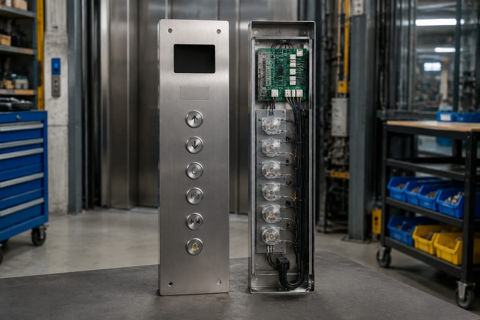
Capacitive elevator buttons detect a change in electrical capacitance when a finger approaches or touches the sensor surface. They have no traditional moving contact and can give a clean, flush appearance.
However, capacitive controls require careful integration. Sensitivity can be affected by moisture, cleaning residues, grounding, protective overlays, gloves and electrical noise. They also need intentional tactile and audible feedback if users cannot rely on physical movement to know their input has registered.
For most like-for-like repairs, retain the original technology. Changing from mechanical to capacitive, or vice versa, is a panel and system modification rather than a simple spare-parts substitution.
Illumination, voltage and feedback
Illumination confirms that a button is available, selected or in a special operating state. The exact behaviour varies by lift controller and button construction. Some buttons are continuously backlit so their legends remain visible; others illuminate only after a call is registered; some use different colours to indicate status.
Common light sources include LEDs and, in older equipment, lamps. A replacement part must be checked for:
- Rated supply voltage and whether it is AC or DC
- LED polarity, where applicable
- Lamp or LED current requirement
- Colour of illumination and the meaning assigned to it
- Common or separate supply for the lamp and switch contacts
- Whether the controller expects a simple contact closure, monitored input or electronic signal
- Connector type, pin order and cable length
Voltage matching is critical. A button designed for one illumination supply may not light correctly, may be damaged or may overload a circuit when fitted to another. Even where an LED module is labelled with a nominal voltage, confirm whether the original circuit supplies regulated DC, alternating current or a board-controlled output.
Feedback should be considered as a complete user interaction. A reliable button may provide one or more of the following:
- A physical click or travel
- Visible illumination
- A buzzer or chime acknowledgement
- Tactile marking for orientation
- A controller display update
Do not assume the button itself creates every feedback signal. Audible acknowledgement and display changes are frequently produced by the controller or panel electronics. Replacing the button alone will not correct a missing chime caused by a controller setting, speaker fault or communication issue.
Button boards and panel communication
Many contemporary lift panels use a button board, serial board or interface PCB behind the visible buttons. Instead of running separate wires from every button to the controller, the board scans inputs, controls illumination and communicates with the lift system through a harness or data connection.
This design can reduce cabling and make a compact panel possible, but it creates a compatibility dependency. The visible button, its LED module and the board must work as an assembly.
For example, a Mitsubishi elevator button board should be evaluated against the existing board reference, connector layout and panel configuration, rather than selected only by the number of buttons. Likewise, a Hyundai BD push button board needs matching mechanical and electrical details before it is installed.
Checks before replacing a button board
Record the following before removing the original board:
- Part number, revision number and any label or barcode.
- Clear images of both sides of the board, connected harnesses and connector keyways.
- Number, arrangement and function of buttons on the panel.
- Display, indicator, buzzer and key-switch connections.
- Supply voltage measured or stated in the panel documentation.
- Whether the controller reports communication errors, input errors or no errors.
- Existing button and LED condition, especially if only one position has failed.
A board fault can resemble several individual button failures, such as an entire row not responding, multiple lamps failing together, incorrect illumination or intermittent operation after vibration. Conversely, a single damaged actuator, loose connector pin or broken flex cable may look like a board failure.
Do not mix button boards from different panel families without documented compatibility. Similar-looking boards can use different input matrices, firmware, serial communication or connector pinouts. Forced installation may damage the board, controller interface or wiring harness.
Accessibility considerations for elevator buttons
Accessible elevator controls need to be easy to locate, understand and operate for users with varying vision, mobility and dexterity. Accessibility is not only about fitting Braille. It depends on the complete panel layout, contrast, button force, feedback and mounting position.
Useful considerations include:
- Tactile floor identification: Raised numerals, characters or tactile symbols help users distinguish controls by touch.
- Braille marking: Where required by the project specification, ensure the language, placement and dot pattern match the approved design. Braille should supplement, not replace, legible visual markings.
- Contrast: The button face, legend and surrounding panel should allow symbols and floor labels to be identified under normal lighting.
- Tactile differentiation: Door, alarm and floor controls should be distinguishable through shape, marking or layout where possible.
- Operating force and travel: A button should register reliably without excessive force.
- Feedback: Visual, audible and tactile confirmation reduces uncertainty after a selection.
- Reach range: The full panel layout must be reviewed, not just the individual button. A correctly specified button is of little value when important controls are difficult to reach.
Requirements may differ by building type, project specification, applicable Indian standards and authority requirements. For a modernisation project, confirm the required arrangement with the lift consultant, building owner or relevant authority before finalising panel artwork or button markings.
Common button failure symptoms
A clear symptom record helps separate a worn button from a wiring, board or controller problem. Inspect only with suitable isolation procedures and authorised personnel, as lift panels contain live circuits and safety-related equipment.
| Symptom | Likely causes | First checks |
|---|---|---|
| Button does not register | Worn contact, broken actuator, loose wire, failed input channel | Compare with another button, inspect mounting and connector, test contact as appropriate |
| Button is physically stuck | Dirt, liquid residue, damaged spring, distorted bezel | Check movement and panel alignment; replace damaged mechanical parts |
| Light does not illuminate | Failed LED/lamp, wrong supply, broken board output, connector issue | Confirm supply and polarity; compare with adjacent working buttons |
| Button stays illuminated | Stuck contact, controller-held call, board output fault | Cancel or complete call, inspect contact state and controller status |
| Several buttons fail together | Harness fault, common supply loss, button-board failure, communication fault | Check common connectors, voltage and diagnostic indications |
| Wrong floor or function responds | Miswired connector, incorrect board, panel mapping error | Stop use for that function and verify pinout, labels and configuration |
| Intermittent response | Loose terminals, fractured solder joint, moisture, vibration damage | Inspect connections and board condition; reproduce fault cautiously |
Repeated pressing is not a fix for intermittent operation. It can hide the fault during testing and worsen mechanical damage. Similarly, spraying lubricant or cleaner into a button assembly may contaminate contacts, optics or printed circuits. Use cleaning materials only as recommended for the installed panel components.
Alarm, emergency communication, fire-service and other safety-related controls require special care. A cosmetic button replacement should never compromise the intended emergency function. Test procedures should follow the site maintenance process and applicable requirements.
How to specify replacement buttons
The most dependable approach is to build a replacement specification from the installed part and panel, then confirm compatibility before ordering. A photo is useful, but it is not sufficient on its own.
Essential information for a replacement enquiry or purchase order
Provide:
- Manufacturer, lift model or controller family where known
- Existing button part number and revision
- Clear front, side and rear photographs
- Panel cut-out dimensions and button face dimensions
- Mounting method: clip, nut, screw, bracket or board-mounted
- Floor legend or function symbol required
- Button shape, bezel finish and face colour
- Illumination colour, source type and rated supply details
- Contact type, terminal layout and connector reference
- Number of terminals or pins
- Tactile, raised numeral or Braille requirement
- Quantity needed and whether it is for a car panel or landing panel
- Any linked board, harness or display part number
Where the original is an older or discontinued design, first determine whether an exact replacement is necessary. A compatible substitute may be viable only when its dimensions, switching characteristics, illumination and panel appearance are acceptable. It must also be tested within the relevant lift system. A substitute that fits the hole but differs electrically can create nuisance faults or damage electronics.
For a practical starting point when the visible button is the failed item, compare the installed sample with a white-and-blue illuminated Otis elevator push button only after confirming the product reference, dimensions and electrical requirements match the application. Brand association alone does not establish interchangeability.
Frequent replacement mistakes
Avoid these common errors:
- Ordering by exterior diameter while ignoring rear depth and retaining method.
- Matching LED colour but not voltage, polarity or wiring arrangement.
- Replacing a single button when the shared board or harness is actually faulty.
- Using the same legend for different functions, especially door controls.
- Treating COP and landing buttons as interchangeable.
- Omitting raised markings or Braille during a panel refurbishment.
- Installing a non-matching board because connectors appear similar.
- Failing to photograph labels and connector positions before removal.
Kelevator supplies multi-brand elevator spare parts for B2B importers, distributors, maintenance contractors and OEM buyers. For a replacement decision, start with the existing part number, panel photographs and electrical details, then compare them against the proposed part's documented dimensions and interface before installation.
Frequently asked questions
Are all elevator buttons interchangeable?
No. Buttons may differ in cut-out size, depth, mounting, contact type, illumination voltage, connector layout, controller communication and tactile markings. An identical-looking button may still be unsuitable.
Why does an elevator button light up but not register a call?
The illumination circuit and the switching circuit can be separate. The LED may receive power while the mechanical contact, input wiring, button-board channel or controller input has failed. Test the complete signal path rather than replacing the lamp module only.
Can a standard push button replace a capacitive elevator control?
Usually not as a direct replacement. Capacitive controls may be integrated with an electronic interface, custom fascia and specific controller logic. Changing technologies generally needs an engineered panel modification.
What should be checked after replacing a button?
Confirm correct mechanical fit, secure terminals, intended illumination, accurate legend, reliable registration, cancellation behaviour and any required audible or tactile feedback. For emergency or restricted controls, follow the authorised site test procedure.
Related product references
For practical catalog examples related to this topic, review [Push Button White Blue light OTIS elevator parts lift accessories](/products/push-button-white-blue-light-otis-elevator-parts-lift-accessories/), [button board Mitsubishi elevator parts lift accessories](/products/button-board-mitsubishi-elevator-parts-lift-accessories/), and [BD Push Button Board HYUNDAY elevator parts lift accessories](/products/bd-push-button-board-hyunday-elevator-parts-lift-accessories/). Confirm the exact model, dimensions, ratings, and connectors before ordering.