
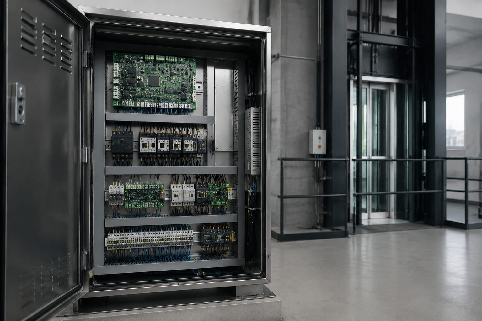
An elevator control panel is the cabinet-mounted control system that receives lift inputs, monitors safety devices and directs the motor, doors, car position and landing calls. When it develops a fault, the right response is not to replace the first board that appears suspect. Technicians should first establish whether the issue is caused by incoming power, a safety-chain interruption, wiring, a peripheral device, configuration or the controller itself.
For maintenance contractors and sourcing teams, a reliable replacement depends on matching the board's function, part number, revision, supply requirements, connector layout and programmed parameters. A physically similar board can still be unsuitable for the installation.
What an elevator control panel does
The elevator control panel, also called a lift controller or controller cabinet, coordinates the operation of the complete lift system. It processes inputs from the car, landings, shaft and machine-room equipment, then sends outputs to the drive, door operator, indicators and other connected devices.
Its main duties normally include:
- Registering car calls and hall calls, then selecting the travel direction and stopping sequence.
- Reading position information from shaft sensors, encoders or an absolute positioning system.
- Controlling acceleration, levelling, stopping and direction commands through the drive interface.
- Managing door opening, closing, reopening and door-zone logic.
- Monitoring the safety circuit before permitting movement.
- Handling overload, inspection, fire service, emergency operation and other configured functions.
- Reporting faults through display codes, LEDs, diagnostic ports or remote-monitoring interfaces where fitted.
The control panel does not create power for every part of the lift. Instead, it controls and supervises circuits that switch or regulate power. The motor drive, braking arrangement, door operator and safety components may each have their own control circuits, but the controller determines when many of them can operate.
In an Indian installation, the panel may be in a machine room, machine-room-less control space, landing cabinet or other approved location. Access and work must be limited to competent lift personnel, with electrical isolation and site safety procedures followed before touching terminals or boards.
Main boards and power components
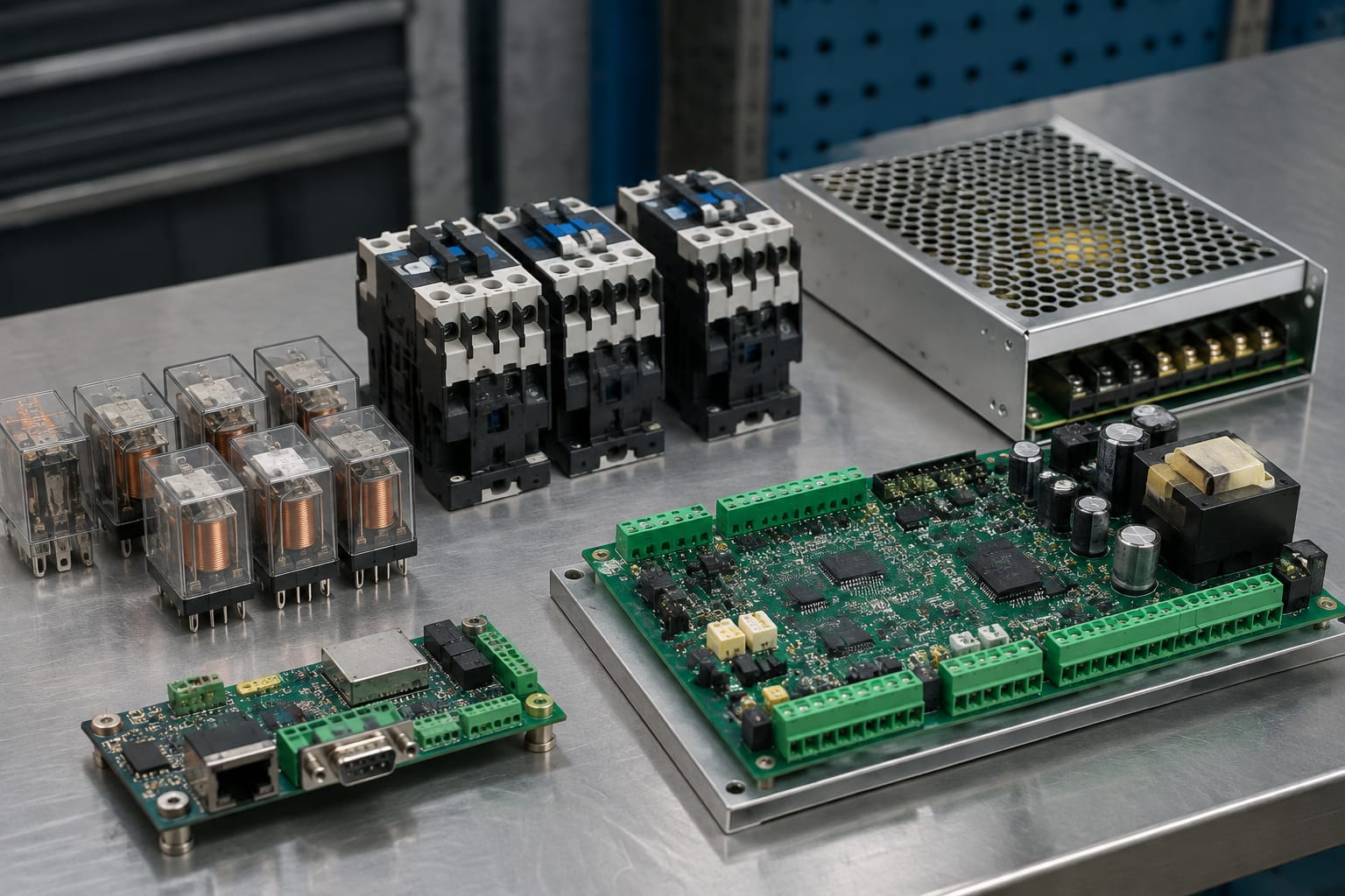
Modern control cabinets generally use modular electronics. Knowing the role of each module makes fault-finding more systematic and purchasing more accurate.
Main controller board
The main controller board is the decision-making board. It runs the lift programme, reads core inputs and issues commands for travel, calls, doors and safety-related states. It may contain a processor, memory, input/output terminals, relays, LEDs, service buttons and communication connectors.
A main board fault can cause a lift to remain out of service, lose calls, display incorrect status, fail to initialise or behave inconsistently. However, these symptoms can also result from a missing supply, failed input device, loose terminal, damaged communication line or corrupt configuration.
When obtaining a replacement, record:
- Manufacturer and controller family.
- Exact board part number.
- Hardware revision and firmware or software version, if shown.
- Cabinet model and lift identification details.
- Terminal labels and connector references.
- Existing parameter backup, service-tool file or configuration record.
- Any option boards, expansion modules and interface boards connected to it.
For multi-brand repairs or modernization stock, an [elevator control motherboard and lift accessory range](/products/5400-elevator-control-motherboard-lift-accessories/) should be assessed against the actual controller information rather than ordered solely from photographs.
Input and output boards
Input boards accept signals from push buttons, limit switches, door locks, safety contacts, position sensors and other field devices. Output boards energise relays, lamps, indicators, door commands and external control circuits.
Some controllers combine these functions on the main board. Others use separate I/O boards to increase the number of connections or separate shaft, car and landing circuits.
A failed I/O channel may look like a failed field component. For example, a landing call that never registers could be caused by the button, the travelling cable, a bus communication issue, an input terminal, the I/O board or an incorrect parameter. Measure and trace the signal before condemning the board.
Power supply unit and protection devices
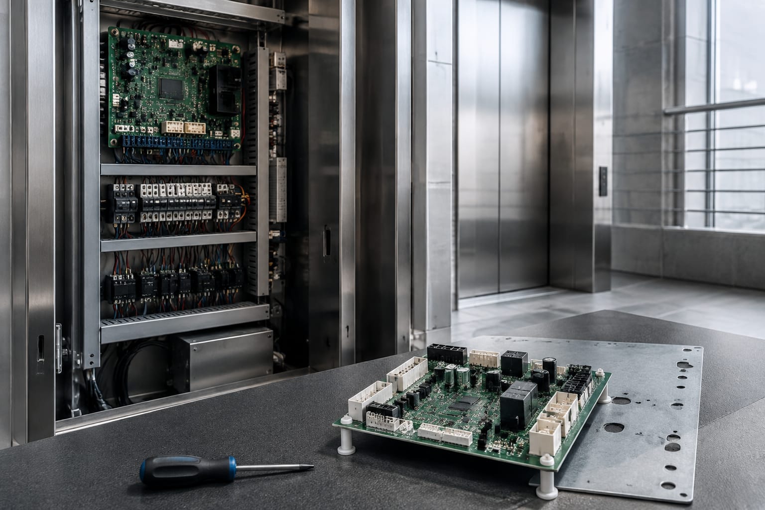
The control electronics require stable low-voltage DC supplies, commonly generated from the incoming cabinet supply. A power supply unit may feed the processor, inputs, communication circuits, displays and relays at different voltages.
Typical associated components include:
- MCBs, fuses and isolating devices.
- Transformers or switched-mode power supplies.
- Rectifiers, DC/DC converters and filter capacitors.
- Earthing terminals and surge-protection arrangements where installed.
- Battery or emergency supply units for alarm, lighting or rescue functions.
Power-related faults can produce random resets, dim LEDs, communication loss, relay chatter or a controller that does not boot. Check supply voltage under load, not only with disconnected equipment. Also inspect for overheated terminals, damaged fuse holders, poor neutral connections and signs of moisture or contamination.
Do not replace a blown fuse with a higher-rated type to keep the lift running. The fuse rating and characteristic are part of the circuit protection design; an incorrect substitute can damage boards or conceal a serious fault.
Drive interface and motor control connection
The controller commonly communicates with a VVVF drive or motor-control arrangement through hardwired signals, relay contacts, analogue signals or a serial interface. The drive may provide ready, run, fault, direction, speed and brake-related status signals back to the controller.
A lift that powers up but will not travel may have a drive fault, a safety-chain issue, missing enable signal, brake circuit problem or controller logic condition. A controller board should be replaced only after the drive's recorded fault information and interface signals have been checked.
Relays, contactors and safety circuits
Relays and contactors provide electrical switching between the controller and higher-power or safety-critical circuits. They are straightforward components, but their condition strongly affects lift availability.
Relays and contactors
Relays are often used for low- and medium-power control switching, while contactors are generally used for higher-current motor and power circuits. Depending on the design, the cabinet may include run, direction, brake, door, inspection, auxiliary and safety relays.
Common issues include:
- Burnt or pitted contacts causing voltage drop or intermittent operation.
- Coil failure due to incorrect supply, heat or age.
- Mechanical sticking from contamination or worn parts.
- Loose control terminals.
- Incorrect replacement coil voltage or contact arrangement.
- A relay driven correctly by the board but unable to switch its load.
Before replacing a relay, verify its coil voltage, contact form, current rating, mounting style and any required suppression device. Replacing it with a similar-looking item can alter circuit behaviour or damage an output board.
Contactors should be inspected for contact wear, overheating, coil condition and mechanical operation. A contactor may appear to pull in but still have poor contacts under load. Electrical tests should be carried out only by appropriately qualified personnel using safe isolation and the manufacturer's procedures.
Safety circuit
The safety circuit is a series of monitored contacts that must be in the correct state before normal travel is permitted. It may include devices such as:
- Car and landing door locks.
- Car-top stop switch and inspection controls.
- Pit stop switch and shaft safety devices.
- Governor, safety gear and buffer switches.
- Final limit switches and other travel-protection contacts.
- Motor or brake monitoring contacts, depending on the system design.
An open safety circuit is one of the most frequent reasons for a no-run condition. The controller may show a safety-chain fault, but that message identifies the circuit state, not necessarily the failed item.
Technicians should follow the wiring diagram and trace the chain section by section. Look for a door lock that does not make reliably, a damaged flexible cable, a disturbed pit switch, a loose terminal or a contact affected by dirt or misalignment. Never permanently bypass a safety device to return a lift to service. Temporary diagnostic methods, where permitted by the manufacturer's procedure, must be controlled and removed before commissioning.
Communication and voice boards
Communication boards connect the controller to devices that exchange data rather than simple on/off signals. These may include car operating panels, landing displays, destination-control equipment, remote monitoring units, door systems and serial shaft networks.
The board type and protocol are often specific to a controller family. A device may use CAN, RS-485, proprietary serial communication or another architecture. Correct wiring, termination, addressing and software configuration are as important as the board itself.
Communication faults may cause intermittent landing calls, blank indicators, unavailable car buttons, repeated resets or loss of multiple devices on the same bus. Inspect the bus cable route, connectors, screen/earthing arrangement as specified, termination components and device addresses before replacing a communication board.
Voice and announcement boards
Voice boards provide spoken floor announcements, travel messages, alarms or other configured audio. They may connect to the controller using a dedicated harness or a communication bus and may work with an amplifier, speaker and stored audio files.
A silent or distorted announcement is not always a failed voice board. Check the speaker, amplifier supply, volume setting, wiring, harness condition and configured announcements. Confirm the required model and revision for the controller when sourcing a replacement. For example, a [lift control-panel voice board](/products/3300-3600-elevator-control-panel-voice-board-vca-11-qd-lift-parts/) should be matched against the installed board label, connector details and system application.
Common control-panel fault symptoms
Symptoms provide a starting point, not a diagnosis. The following table helps separate likely areas for investigation.
| Symptom | Possible causes to check first | Replacement decision |
|---|---|---|
| Controller display is blank | Incoming supply, MCB, fuse, transformer/PSU output, display harness | Replace the display or controller only after correct supply is confirmed |
| Lift will not move | Safety circuit, drive fault, inspection mode, stop switches, brake circuit, controller enable | Do not assume the main board is faulty from a no-run condition alone |
| Lift stops at the wrong level | Encoder or sensor issue, magnet/target alignment, shaft wiring, parameter loss | Verify position feedback and learn/setup data before changing the board |
| Doors fail to close or reopen repeatedly | Door protection device, door locks, operator fault, door-zone signal, wiring | Check the door operator and lock circuit before the controller output |
| Calls do not register | Button, COP/LOP board, bus wiring, I/O input, addressing, configuration | Trace the affected signal path and compare with a working call |
| Random resets or intermittent faults | Low-voltage supply instability, loose terminals, heat, earthing, communication noise | Replace electronics only after supply quality and connections are checked |
| Multiple indicators or panels fail | Bus supply, communication trunk, termination, addressing, central interface board | Investigate shared circuits before individual field devices |
| Fault recurs after a new board | Incorrect parameters, external short, wrong revision, uncorrected field fault | Reassess compatibility and root cause before replacing another board |
Error codes are useful only with the relevant controller documentation. The same code format can mean different things across brands and generations. Record the full code, time of occurrence and operating condition before resetting the controller, as resets can erase useful evidence.
Diagnostic checks before replacement
A disciplined check reduces unnecessary board replacement and prevents damage to new electronics. The exact process depends on the manufacturer, but the sequence below is broadly applicable.
1. Make the site safe and preserve fault information
Use approved isolation, lockout and inspection procedures. Record controller fault history, LED status, display messages, drive faults, current parameters and any recent work carried out. Photograph terminal positions and board connections only where site rules permit.
A board replacement without a configuration backup can create a longer outage than the original fault. Preserve data before disconnecting a functioning or partly functioning controller.
2. Confirm incoming and low-voltage supplies
Check the cabinet's incoming supply and the outputs from transformers or power supplies against the equipment documentation. Examine fuses, protection devices, terminals and earthing. Test under normal load where safe and appropriate.
If a supply collapses when a relay or peripheral operates, investigate the load and wiring. Fitting a new controller board into an unstable supply environment risks immediate repeat failure.
3. Check the safety chain and operating mode
Verify whether the lift is in normal, inspection, emergency or another special mode. Trace the safety circuit using the correct schematic and identify the open segment. Check car-top, pit and machine-area stop devices, door locks and other relevant contacts.
Do not use a generic wiring assumption. Terminal designations and safety-chain architecture vary significantly by controller.
4. Isolate the affected function
Compare a non-working function with a working equivalent. For a single unregistered landing call, trace the button, local board, bus connection and input status. For a door issue, compare the controller command, operator response and door-lock feedback.
This approach narrows the fault to the input side, controller logic, output side or connected equipment. It is more dependable than replacing boards based on visible symptoms.
5. Inspect boards and connectors carefully
With power isolated, inspect for loose plugs, oxidised pins, heat damage, swelling capacitors, cracked solder joints, moisture traces and insect or dust contamination. Reseat connectors only when permitted and when their orientation has been documented.
Do not clean boards with unsuitable solvents or use excessive force on fine-pitch connectors. Electrostatic precautions are important for processor and communication boards.
6. Decide whether repair, exchange or replacement is justified
Replacement is appropriate when the diagnosis supports a failed board and the correct compatible part is available. Repair may be viable for certain components through a suitably capable specialist, but it must not compromise safety-related functionality, software integrity or traceability.
For older controllers, modernization may be more practical than repeated board-level replacement where parts are obsolete, configuration is unavailable or multiple modules are failing. This decision should account for the condition of the drive, door system, fixtures, shaft wiring and the expected scope of integration work.
Board and connector compatibility
Compatibility is the central purchasing issue for an elevator control panel board. Brand name alone is not enough, and neither is a matching cabinet photograph.
What to verify before ordering
Use this checklist for every board, module or panel replacement:
- Exact manufacturer part number and visible board revision.
- Controller family, cabinet model and application.
- Firmware version and whether programming is required before use.
- Input/output count, voltage levels and signal type.
- Connector number, keying, pin arrangement and harness orientation.
- Communication protocol, bus address and termination requirements.
- Door operator, drive and position-system interfaces.
- Required safety functions and configured operating modes.
- Physical mounting points, dimensions and enclosure clearance.
- Whether a replacement board is new, repaired, exchange or an approved equivalent.
- Parameter transfer method, service-tool access and licence requirements where applicable.
A later board revision may be compatible only with a matching software release or additional harness change. Conversely, an older revision may not support the existing peripherals. Ask for technical confirmation based on the equipment data, not merely the board photograph.
Connector matching is more than plug fit
A connector that fits physically may carry a different pin assignment. Applying the wrong voltage or signal to a board can damage it immediately. Check connector labels, circuit diagrams and pin-outs. Never move plugs between similar boards unless the manufacturer documentation confirms the arrangement.
It is also important to inspect the existing harness. A failed connector, loose crimp, overheated terminal or damaged screen can create symptoms that appear to be a board fault. Replacing only the board leaves the original problem in place.
Direct replacement versus modernization
A direct replacement retains the existing controller architecture and is usually preferred when the failed component is identifiable, supported and compatible. It may minimise changes to wiring and fixtures, but it does not address wider ageing issues.
Modernization replaces some or all of the control system. It can be considered when the controller is obsolete, recurring faults affect several modules, documentation is unavailable or building requirements have changed. It requires more planning because compatibility must be checked across the motor drive, door operator, car and landing fixtures, travelling cable, position system and safety devices.
For door-related modernization or repair work, selecting a [Toshiba elevator door control panel and door parts](/products/toshiba-elevator-door-control-panel-lift-door-parts/) should begin with verification of the installed door system, board markings and connection arrangement. A panel intended for another door operator variant may not perform correctly even within the same brand family.
Commissioning repaired or upgraded controls
Commissioning proves that a repaired or replaced control system operates correctly in its actual installation. It is not limited to switching the lift on and observing one journey.
The work should be carried out by competent personnel using the applicable manufacturer instructions, building requirements and project method statement. The scope varies by equipment, but normally includes the following.
Restore settings and verify configuration
Load or enter the correct parameters only from a verified source. Confirm lift type, number of floors, stopping pattern, drive interface, door timings, position system, car and landing calls, indicators, alarm functions and configured special modes.
Incorrect settings can cause unsafe or unreliable operation even where all boards are electrically sound. Maintain a record of the final parameter set, board revision and date of work for future servicing.
Test movement, levelling and doors
Under controlled conditions, test travel in both directions, each landing stop, levelling accuracy, normal door cycles, reopening devices, door-lock feedback and relevant car/landing calls. Observe for intermittent faults during repeated operation, not only the first successful run.
Where a board has been replaced after a position-related fault, confirm shaft learning or calibration procedures as specified by the controller manufacturer. Do not rely on a previous position table unless it has been verified for the installed system.
Prove safety and emergency functions
Test the relevant safety functions according to the approved procedure. This can include stop switches, door interlocks, inspection controls, overspeed and travel-protection interfaces, alarm communication, emergency lighting and rescue operation where fitted.
Safety devices must be returned to their intended operating condition after testing. Any temporary test arrangement must be removed, and all cabinet covers, guards and labelling restored before handover.
Monitor and document the result
Review fault logs after commissioning and confirm that there are no unresolved active errors. Record replaced part numbers, board revisions, configuration changes, measured values where relevant and outstanding recommendations.
For a repaired panel, monitoring during the next scheduled maintenance visit can help identify heat, vibration, supply or intermittent connection issues that were not evident during initial testing.
FAQ
Can any elevator control board be replaced with an equivalent board?
No. An equivalent must match the function, electrical interface, connectors, communication protocol, software requirements and application configuration. A board with a similar appearance or product description is not automatically interchangeable.
How do I know whether the main controller board has failed?
First confirm that the controller has correct power, the safety circuit is complete, operating modes are correct and field inputs are reaching the board. Then check diagnostic LEDs, fault history, outputs and known-good peripheral signals. A confirmed failure usually requires evidence that the board is not processing valid inputs or producing the expected output.
Can a used control board be installed?
It may be technically possible, but the risks need assessment. Verify exact identity, revision, condition, software, configuration and prior application. A used board may retain incompatible parameters or have an unknown fault history. It should be commissioned and tested as thoroughly as any other replacement.
Does replacing a board require programming?
Often, yes. Some boards store parameters, floor data, door settings, addresses or firmware-specific configuration. Even where settings are retained elsewhere, the replacement may require setup, software transfer or configuration checks before the lift can operate correctly.
A practical next step is to collect the controller and board labels, fault records, cabinet photographs and relevant wiring details before sourcing. Kelevator supplies multi-brand elevator spare parts for B2B importers, distributors, maintenance contractors and OEM buyers; provide the verified technical information so the replacement can be assessed against the installed system.