
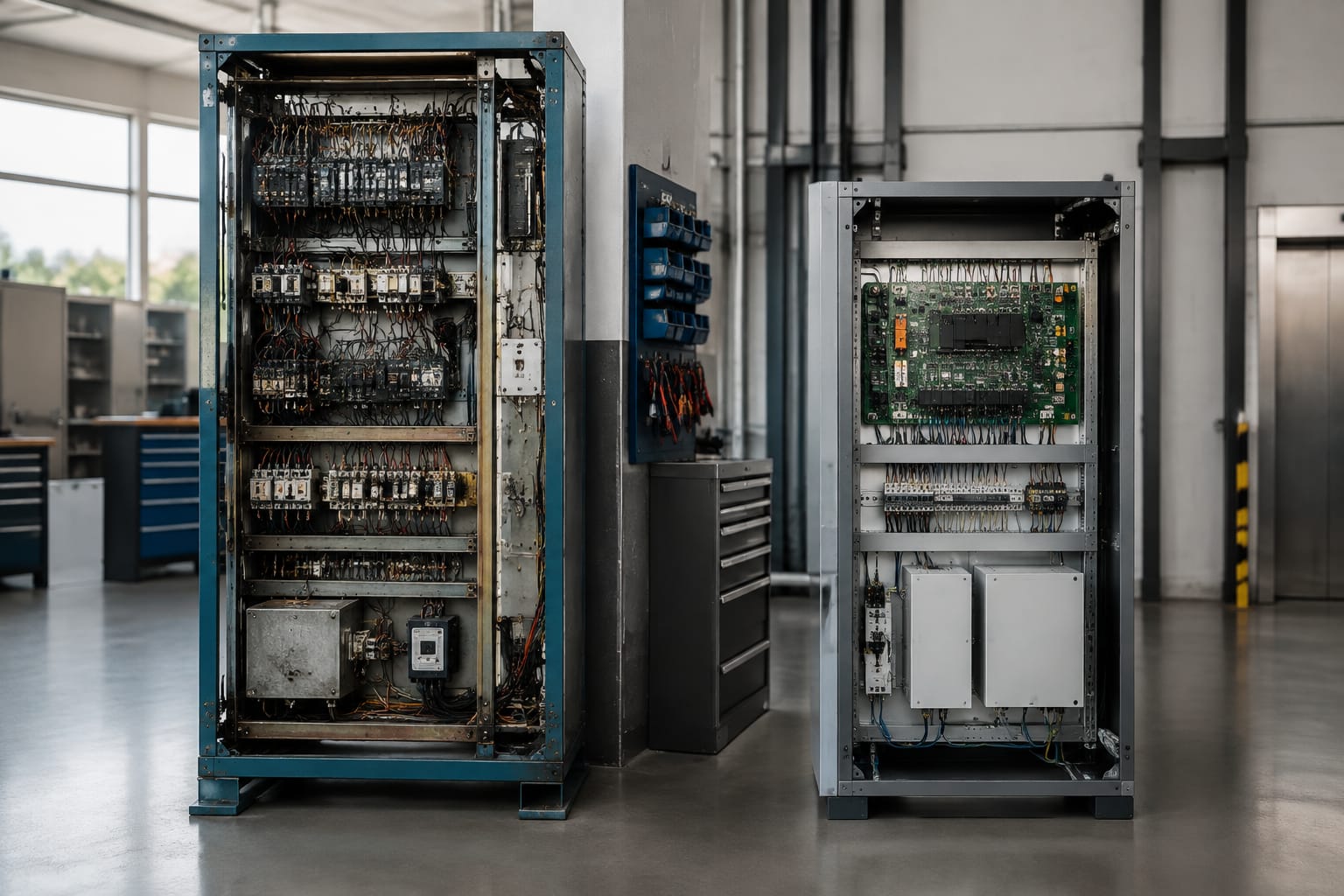
An elevator controller is the decision-making unit of a lift system. It receives calls, door and safety signals, determines the next movement, commands the drive, and records or communicates operating status. Choosing one is therefore not simply a matter of matching a cabinet size or replacing an obsolete board. The new controller must suit the lift application, connected equipment, safety arrangement and future maintenance needs.
For a replacement or modernisation, start by documenting the existing installation: lift type, motor and drive data, door operator, landing signals, travelling cable, safety chain, shaft layout and any group-control or access-control requirement. This information determines whether a controller can be retained with selected components, needs interface modules, or requires a broader upgrade.
What an elevator controller manages
The elevator controller coordinates normal operation, fault handling and safety-related functions within the lift system. In a traction lift, it works closely with the VVVF drive or motor-control arrangement to control acceleration, deceleration, levelling and stopping. In a hydraulic lift, it controls the pump unit, valve functions and relevant levelling signals.
Typical controller responsibilities include:
- Registering car calls and landing calls.
- Determining travel direction, stopping sequence and parking behaviour.
- Monitoring position through sensors, encoders, magnetic switches or a shaft-information system.
- Operating door open, close, dwell and re-open commands.
- Checking the safety chain and preventing movement when safety conditions are not satisfied.
- Managing levelling and re-levelling where the system design supports it.
- Communicating with car operating panels, landing indicators, drives, door operators and remote monitoring equipment.
- Providing diagnostic messages, event records and maintenance functions.
The exact division of responsibility varies by design. A modern integrated controller may handle most logic in software, while an older system may distribute it between relay circuits, separate boards and electromechanical devices. Before replacing any part, establish which device currently owns each function. An apparent controller fault can originate in the drive, door circuit, encoder, travelling cable or safety circuit.
Relay-based, PLC and integrated controls
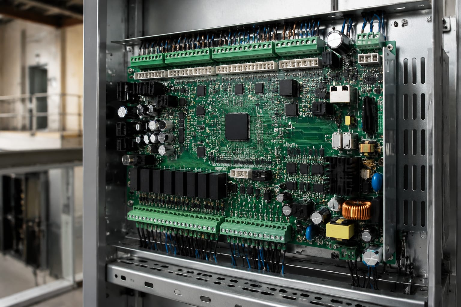
Controller technology affects maintainability, diagnostic capability, retrofit options and the availability of spares. It does not, by itself, determine lift quality. The condition and compatibility of the full installation remain decisive.
| Controller type | Typical characteristics | Strengths | Limitations and replacement considerations |
|---|---|---|---|
| Relay-based | Electromechanical relays, contactors, timers and extensive point-to-point wiring | Logic is visible to experienced technicians; individual electrical components may be replaceable | Large panels, ageing contacts, limited diagnostics and difficult fault tracing; a direct modern equivalent is rarely practical |
| PLC-based | A programmable logic controller with input/output modules, usually alongside relays and contactors | Flexible logic changes and familiar industrial components in some systems | Program access, software backup and proprietary wiring conventions can be barriers; verify lift-specific safety and motion functions |
| Integrated microprocessor control | Dedicated lift controller board with digital communication, configurable parameters and diagnostic tools | Compact installation, richer diagnostics, improved signal options and easier feature integration | May depend on manufacturer tools, specific serial protocols and compatible peripheral boards; configuration must be controlled carefully |
Relay-based controllers
Relay controllers are still found in older residential, commercial and industrial buildings. Their logic is created by wiring, relay contacts and timers. An experienced maintenance technician can trace the circuit physically, but age creates risks: oxidised contacts, worn relay coils, brittle insulation, altered wiring and undocumented modifications.
A relay controller can sometimes be kept operational through targeted repairs. However, a full controller replacement is often more sensible when repeated faults, unavailable parts, poor documentation or high maintenance time outweigh the benefit of retaining it. Modernisation usually involves retaining only equipment that has been inspected and proven compatible, such as certain motors, door operators or indicators.
PLC-based controllers
Some installations use PLCs for lift logic, often in specialised applications or earlier modernisations. A PLC can be robust, but its suitability depends on the quality of the original design and documentation. A replacement decision should include access to the programme, software version, PLC hardware model, I/O mapping and electrical drawings.
Do not assume that any industrial PLC can replace a dedicated elevator controller. Lift applications require defined interfaces for motion, doors, position and safety circuits. The selected hardware and design must be appropriate to the installation and applicable requirements.
Integrated microprocessor controllers
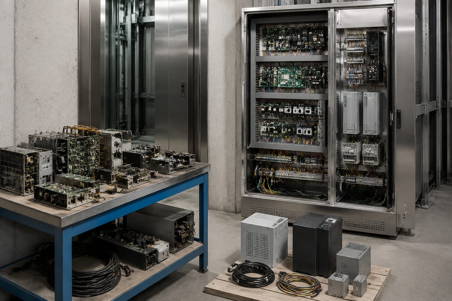
Most current controller replacements use dedicated, microprocessor-based lift controls. These can support serial car and landing communication, fault logs, programmable service settings, battery rescue interfaces, access control and group operation where compatible equipment is used.
The benefit is not merely more features. A well-selected integrated controller can simplify diagnosis and reduce the number of ageing relay logic elements. However, an integrated controller is not universally interchangeable. Confirm its supported drive protocol, encoder or position system, door interface, display communication and safety-chain arrangement before procurement.
Traction versus hydraulic applications
The lift drive system is the first selection filter. A controller intended for a traction machine cannot simply be applied to a hydraulic power unit, and vice versa.
Traction lift controllers
Traction lifts may use geared or gearless machines, with AC drives commonly used for speed control. The controller must be compatible with the installed drive or with the replacement drive selected for the project. Key checks include:
- Motor type, rated voltage, current, power and speed.
- Drive make, model and control interface.
- Whether commands are hardwired, analogue, serial or through a proprietary protocol.
- Encoder type and feedback arrangement, where fitted.
- Brake control circuit, brake monitoring and contactor arrangement.
- Shaft position system, terminal limits and levelling devices.
- Machine-room, machine-room-less or overhead controller placement.
Where the existing VVVF drive is retained, obtain its parameter backup and interface wiring details. Reusing a working drive can reduce scope, but only if the controller can communicate with it correctly and the drive remains supportable.
Hydraulic lift controllers
Hydraulic systems use a controller to operate the motor starter, pump motor, valves and levelling arrangement. Selection should account for:
- Star-delta, direct-on-line or other motor-starting method.
- Valve coil voltages and available valve functions.
- Down and up levelling configuration.
- Motor thermal protection and pump run-time monitoring.
- Emergency lowering arrangement.
- Oil temperature or pressure-related signals, if fitted.
- The nature of any rescue or battery-backed operation.
Hydraulic modernisation can improve reliability where controls are ageing, but it will not correct mechanical issues such as valve wear, cylinder concerns or unsuitable oil condition. Separate controller work from hydraulic equipment inspection in the scope and records.
Door and car-top control interfaces
Door faults account for a significant share of lift callbacks, so door compatibility deserves the same attention as drive compatibility. The controller must work with the existing car door operator and any landing-door monitoring arrangement.
Document whether the door operator receives simple open, close and common signals, or communicates digitally. Also identify its supply voltage, safety-edge or light-curtain connection, nudging function, door-zone signals and locking contacts. Reusing an older door operator is possible only when its condition and electrical interface are suitable.
At the car top, the controller connects through the travelling cable to equipment such as:
- Car operating panel and emergency controls.
- Door operator and car-door contacts.
- Inspection station and stop switch.
- Car-top safety devices.
- Load-weighing system, if installed.
- Position and door-zone signals, depending on architecture.
- Car fan, light, alarm and intercom interfaces where applicable.
A travelling cable with insufficient cores or degraded insulation can limit an otherwise suitable upgrade. Serial communication can reduce the number of required cores, but it introduces protocol compatibility and termination requirements. Do not promise serial reuse until the car and landing devices have been identified.
For installations adding credential-based entry, confirm where the access-control decision will sit. An [elevator access-control motherboard](/products/5500-elevator-acess-control-board-motherboard-id-lift-parts/) may be relevant where the controller and access system require a compatible interface, but its electrical and communication requirements must be checked against the chosen controller.
Inputs, outputs and safety circuits
Controller specifications often list input/output counts. These figures are useful, but they are only the start of the assessment. Each point must have the correct voltage, signal type, isolation and intended use.
Map every required I/O point
Prepare an I/O schedule from the existing drawings and a physical site survey. It should identify:
- Car and landing call inputs.
- Position, levelling, terminal and door-zone inputs.
- Door-lock, gate-switch and safety-chain contacts.
- Drive-ready, drive-fault, inspection and brake-monitoring signals.
- Door open, close, nudging and supply outputs.
- Indicators, gong, arrows, display and car-light outputs.
- Alarm, intercom, rescue and monitoring connections.
- Fire, access control, emergency power or building interfaces where installed.
Allow spare capacity for legitimate future requirements, but do not select a controller based on point count alone. Mixed-voltage circuits, shared commons, normally open versus normally closed logic, and dry-contact versus powered outputs all need verification.
Treat safety circuits as a design-critical interface
The safety chain typically includes series-connected safety contacts and devices that must be in the correct state before normal movement is permitted. Its exact arrangement differs by lift design. A replacement controller must accept and supervise the installed safety circuit as required by the system design.
Never bypass, bridge or permanently alter a safety device to make a new controller run. A temporary jumper used during controlled commissioning must be removed and verified before handover. If the safety circuit is unclear, damaged or modified over time, it needs proper investigation and rectification, not assumption.
Also distinguish between safety-related circuits and ordinary control inputs. For example, a landing call input and a door-lock contact may both appear as electrical signals, but they do not carry the same consequence or require the same treatment.
Selecting replacement controller hardware
The right replacement controller is one that can be commissioned, maintained and documented for the specific lift. Use a written compatibility process rather than relying only on photographs of the old cabinet.
Minimum information to collect before ordering
- Record the controller, drive, door operator and indicator make and model, including readable labels.
- Identify the lift application: passenger, goods, hospital, home lift or another specialist use.
- Note floors, entrances, rated speed, rated load and car configuration.
- Photograph and trace the terminal wiring, safety-chain path, contactors, transformer and power supply.
- Confirm the motor and drive electrical data from nameplates and existing settings.
- List all connected devices and non-standard functions, including access control, fire interface, emergency power and group operation.
- Obtain wiring diagrams, parameter backups and fault history where available.
- Inspect the cabinet environment for heat, moisture, dust, vibration and earthing condition.
Selection criteria that matter in practice
Application compatibility: Confirm that the controller supports the lift type, number of stops, entrances and operating arrangement. A controller for a simple single-car installation may not suit collective control, duplex operation or a complex door layout.
Drive integration: Decide whether to retain, reconfigure or replace the drive. Compatibility should be confirmed at signal and protocol level, not assumed from matching voltage alone.
Peripheral compatibility: Verify car panels, landing indicators, push buttons, displays, door operators, load-weighing equipment and rescue systems. Reusing existing fixtures may require interface boards or rewiring.
Serviceability: Check diagnostic access, error logging, parameter backup method, manuals, wiring documentation and availability of trained technicians. A controller that only one person can configure creates a long-term operating risk.
Power and environmental conditions: Verify supply voltage, phase arrangement, transformer requirements, cabinet cooling, earthing and surge protection needs. Electrical supply quality can contribute to recurring electronic failures.
Spare-part strategy: For maintenance contractors, distributors and OEM sourcing teams, identify components likely to be needed during service: controller board, power supply, input/output modules, contactors, relays, encoder interface and compatible display or communication boards. Kelevator supplies multi-brand elevator spare parts for B2B buyers, so a component enquiry should include the exact model, photographs and electrical details rather than only the lift brand.
Compliance and responsibility: The modernised installation must be assessed against applicable local requirements, building obligations and the project specification. Responsibility for engineering, installation, testing and approval should be explicit in the contract documents.
Planning a controller modernisation
Controller modernisation is best planned as a controlled system change. The aim is to retain sound equipment where appropriate while replacing obsolete or unreliable controls without introducing undocumented interfaces.
Define the scope before shutdown
A controller-only replacement may include the cabinet, controller board, selected contactors, wiring changes and configuration. A broader modernisation may also include the VVVF drive, encoder, door operator, car panel, landing fixtures, travelling cable, rescue device and communication system.
Make the boundary clear. For example, retaining an old door operator can keep the initial scope smaller, but it may leave a separate source of future faults. Conversely, changing every component may increase downtime and commissioning complexity. The practical decision depends on condition, compatibility, spare availability and the building's operating needs.
Build a migration plan
A workable plan normally includes:
- A pre-survey with marked drawings and terminal references.
- A complete list of retained, replaced and interface components.
- Wiring diagrams for both power and control circuits.
- Parameter sheets for the old drive and the new controller.
- A method for backing up software, settings and fault records before work begins.
- A shutdown and access plan that considers the building's lift availability.
- A commissioning checklist with clear responsibility for each test.
- A handover pack for the maintenance team.
Avoid changing controller logic, drive parameters and door settings simultaneously without recording the original state. When a fault appears afterwards, uncontrolled changes make diagnosis slow and inconclusive.
Plan for signals and access features early
Access control, destination functions, attendant operation, fire recall, emergency power and remote monitoring should be defined before controller procurement. These features can affect I/O allocation, serial bus design, car-panel wiring and software settings.
For a project requiring conventional access-control hardware, review the required reader, relay, power and controller interfaces before selecting a board. Relevant options may include an [elevator access-control board and motherboard](/products/elevator-access-control-board-motherboard-lift-accessories/), subject to model-specific compatibility verification.
Commissioning and documentation
Commissioning is the point at which a correct hardware selection becomes a reliable installation. It should be performed by competent personnel using the selected controller's documentation and the project test procedure.
Commission in a controlled sequence
Start with visual inspection and power checks. Confirm protective earthing, supply conditions, terminal tightness, segregation of power and signal wiring, correct fusing, and the absence of loose conductors. Then validate the safety chain, inspection controls and direction of travel before normal automatic operation.
A practical commissioning sequence includes:
- Verify controller configuration against the documented lift layout.
- Check each shaft position and terminal input individually.
- Test machine and drive control, including brake behaviour and fault response.
- Check car and landing calls at every served floor.
- Test door opening, closing, re-opening, nudging and lock monitoring.
- Confirm floor levelling and re-levelling behaviour where applicable.
- Test inspection, stop switches, alarm and emergency operating functions.
- Verify specified building interfaces, access controls and indicators.
- Review fault logs and correct wiring or parameter issues before handover.
- Complete the required tests and approvals for the installation.
Do not treat a successful run between two floors as evidence that the job is complete. Intermittent inputs, terminal behaviour, door protection, emergency operation and abnormal conditions must be checked according to the project requirements.
Produce a usable handover record
The maintenance team needs more than a controller manual. Handover documentation should include final wiring diagrams, I/O schedule, controller and drive parameters, software or configuration backup method, component models, fault-code information, test records and a list of retained equipment.
Label terminals, relays, contactors and modules clearly enough for future fault finding. Record any interfaces that remain proprietary or depend on a particular configuration tool. This reduces risk when maintenance responsibility changes.
Where door-operator integration is part of the scope, a compatible [multi-function elevator operator interface](/products/universal-elevator-multi-function-operator-monarch-step-system-elevator-parts/) may be considered only after checking the operator model, voltage, command signals and installation instructions.
FAQ
Can an old relay controller be replaced while keeping the existing lift motor?
Often, yes, provided the motor, machine, brake circuit, position system and selected drive or starter arrangement are in sound condition and can be integrated safely. The decision requires electrical data, inspection and a documented interface design. A controller replacement does not automatically resolve mechanical or motor-related defects.
Is an elevator controller universal?
No. Some controllers are flexible across many lift configurations, but no controller is universally compatible without configuration and, in many cases, interface work. The drive, door operator, position system, indicators, safety chain and additional features must all be checked.
Should the VVVF drive be replaced with the controller?
Not always. Retaining a healthy, supportable drive can be practical when the new controller has a verified interface. Replace it when it is unreliable, obsolete, unsupported, incompatible or unable to meet the project’s operational requirements. Record the decision and its technical basis.
What is the most common controller replacement mistake?
Ordering from the existing controller model alone. The replacement must match the whole lift system, not just the old panel. Missing information about the drive, door operator, travelling cable, safety chain or special functions is a frequent cause of delay and additional site work.
For a replacement or modernisation, prepare the site survey, I/O schedule and equipment photographs before requesting hardware options. This gives contractors and sourcing teams a sound basis to compare compatible controller, interface and spare-part choices.