
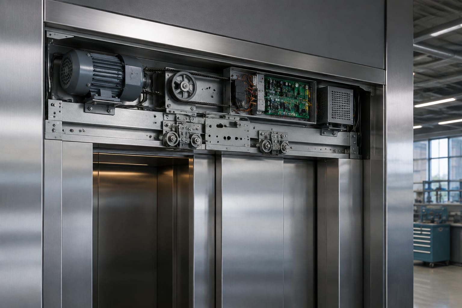
An elevator door drive is the door operator system that opens, closes and monitors lift doors at each landing stop. It combines a motor, controller or drive board, belt or linkage, feedback device, limits and safety inputs so that the car door moves at the intended speed and reverses or reopens when required.
For maintenance and replacement work, a door drive should be treated as a matched system rather than a motor alone. A motor that fits physically may still be unsuitable if its voltage, feedback method, controller parameters, reduction arrangement or wiring does not match the existing operator. Record the original labels, connectors and settings before removing any part.
Parts of an elevator door drive
The term door drive is commonly used for the complete car-door operator, although some suppliers use it specifically for the motor and electronic board. Its usual parts are:
- Door motor: Produces rotational motion for opening and closing.
- Door controller or drive board: Supplies and regulates motor power, reads inputs and controls movement.
- Reduction mechanism: May include a gearbox, pulley arrangement or direct-drive transmission, depending on the operator design.
- Timing belt, toothed belt or cable: Transfers motor movement to the door hanger or coupling mechanism.
- Door vane and landing-door coupling parts: Engage the landing door when the car is accurately levelled at a floor.
- Hangers, rollers and door track: Support the panels and determine whether they can travel freely.
- Clutch, eccentric roller or pick-up mechanism: Coordinates opening of the car and landing doors.
- Encoder, tachometer or Hall sensor: Sends motor position or speed feedback to the controller.
- Open and close limits: Confirm the end positions where fitted. Some modern systems learn travel electronically instead.
- Door protection device: Usually an infrared light curtain, detector edge or safety sensor that prevents closure on an obstruction.
- Door zone, lock and interlock inputs: Allow movement only when the lift is in the correct position and safety circuit conditions are met.
The operator drives the car door directly. The car door then picks up the landing door through its coupling arrangement. A door drive fault can therefore appear as a landing-door problem, but worn sill grooves, damaged hangers, tight rollers or incorrect clutch adjustment may be the underlying cause.
Before diagnosing electronics, inspect the mechanical path. A controller cannot reliably compensate for bent panels, contaminated tracks, failing rollers or an over-tight belt.
AC, DC, and PMSM door motors
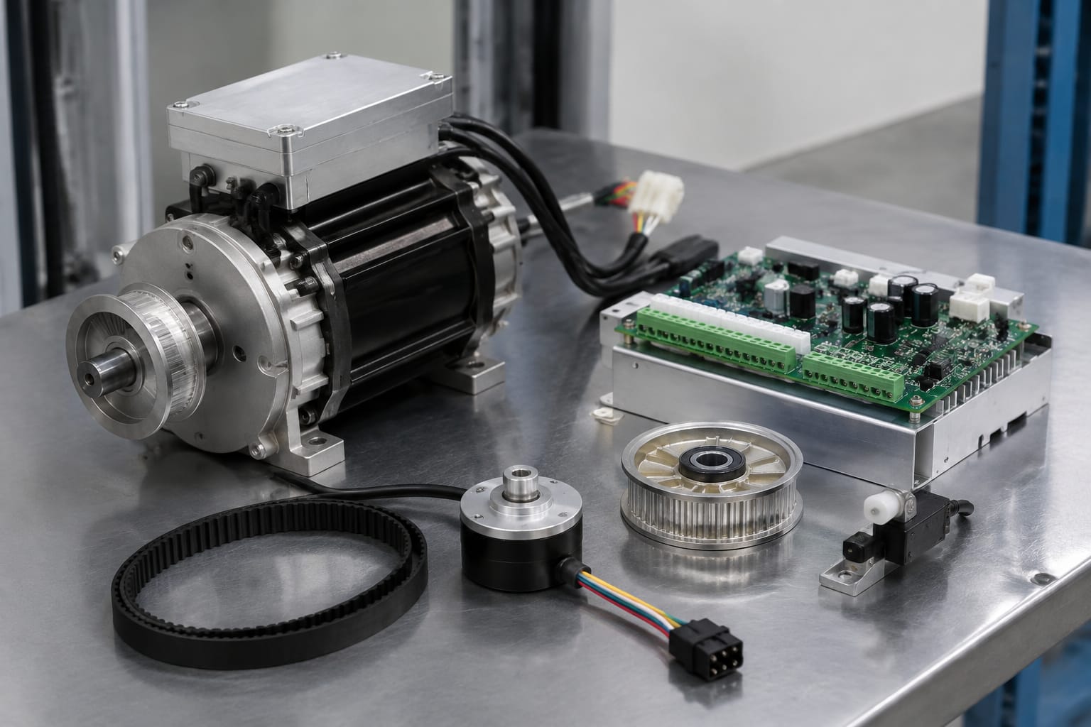
Elevator door motors are commonly categorised by the way they are powered and controlled. The correct choice depends on the installed door operator and its board, not simply on the motor type preferred by the buyer.
| Motor type | Typical characteristics | Main advantages | Important replacement checks |
|---|---|---|---|
| AC induction motor | Usually operated with capacitors, relays or an AC control arrangement | Simple construction; widely encountered on older operators | Rated voltage, frequency, capacitor circuit, winding arrangement, rotation and speed |
| Brushed DC motor | Uses brushes and commutator; controlled by varying DC voltage or PWM | Good starting torque and straightforward speed control | Nominal voltage, polarity, brush condition, shaft dimensions, encoder provision and current rating |
| PMSM / brushless permanent-magnet motor | Electronic commutation using position feedback and dedicated drive electronics | Precise speed control, compact arrangement and no brushes to replace | Controller compatibility, encoder or Hall feedback type, phase order, motor constants and connector pinout |
AC door motors
AC motors are found in many conventional door operators. Their speed behaviour depends on the mains frequency, poles, gearbox or pulley ratio, and the controller arrangement. A single-phase motor may use a start or run capacitor, while other designs use electronically controlled AC power.
Do not substitute a visually similar AC motor without checking the winding configuration and capacitor requirements. An incorrect capacitor value or winding connection can reduce torque, overheat the motor or produce inconsistent direction changes. Also confirm whether the original operator uses an external brake, as this affects stopping and holding behaviour.
Brushed DC door motors
Brushed DC motors are common where the controller needs smooth variable speed and high starting torque. The board regulates motor voltage and direction, often using an H-bridge circuit. Many units include an encoder on the rear shaft or within the motor assembly.
Brush wear, commutator contamination and weak springs can cause intermittent operation, sparking, low torque or erratic encoder signals. A motor may run freely on a bench but fail under a loaded door if the brushes are worn or the mechanical operator is tight.
Voltage is a critical compatibility point. Connecting a lower-voltage DC motor to a higher-voltage board can cause rapid damage; using a higher-voltage motor with an unsuitable board may result in weak movement or failure to complete the door cycle.
PMSM and brushless door motors
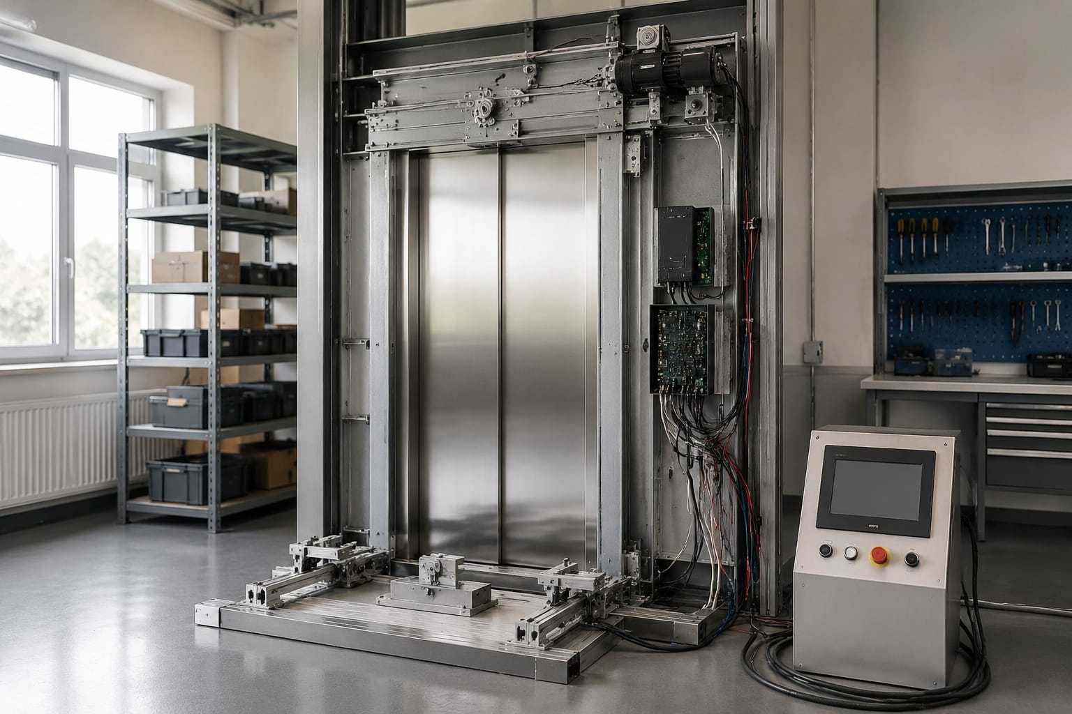
Permanent-magnet synchronous motors (PMSM) and other brushless designs rely on a compatible electronic controller. The board energises motor phases in sequence based on rotor-position feedback, typically from Hall sensors or an encoder. A brushless motor cannot normally be operated correctly from a controller intended for a simple brushed DC motor.
These motors can provide controlled acceleration, deceleration and obstruction response, but their compatibility requirements are stricter. Match the feedback device, phase wiring, rated current, supply arrangement and motor-specific parameters. Interchanging feedback plugs or phase leads without verified documentation can cause vibration, reverse rotation, no start or controller faults.
Door controllers and drive boards
The door controller, often called a door drive board, is the decision-making and power-control unit for the operator. It receives commands such as open, close, nudging or re-open from the lift controller, then monitors the door position, current and safety inputs while powering the motor.
Depending on the operator, a board may include:
- A rectifier and DC power supply section
- Motor power transistors, relays or a frequency-control stage
- Inputs for open, close and door-zone signals
- Connections for light curtains, detector edges and safety circuits
- Encoder, Hall sensor or limit-switch inputs
- Parameter switches, potentiometers, push buttons or a service interface
- Fault LEDs or display indications
- Outputs for door status and lock-related signals
A drive board must be compatible with both the motor and the door operator logic. Connector shape alone is not sufficient evidence. Boards with similar layouts may differ in supply voltage, communication wiring, input logic, motor output stage or firmware.
When sourcing a board, capture clear details from the removed unit:
- Manufacturer, operator model and complete board part number.
- Revision code, firmware label and any programming key or chip reference.
- Supply rating and input/output terminal markings.
- Motor type and motor label details.
- Connector count, keying, pin arrangement and harness part numbers.
- Existing parameter positions or displayed settings.
- The exact fault symptom that led to replacement.
For example, a replacement should be evaluated against the original operator documentation and observed wiring, even when looking at a Hitachi elevator door motor drive board. Product images and broad descriptions are useful for identification, but the final match must be made against the installed part number and specification.
Do not condemn the board immediately when a door fails to close. A blocked light curtain, misaligned limit, broken encoder cable, worn belt or high door friction can make a functioning controller stop or reverse the door as designed.
Feedback, limits, and safety sensors
Feedback lets the controller regulate door travel rather than simply applying power for a fixed time. The feedback method affects both performance and replacement compatibility.
Encoders and Hall sensors
An encoder reports shaft movement as pulses, allowing the controller to determine speed and relative position. Incremental encoders require the board to count pulses from a known reference, while other designs may use additional index signals. Hall sensors report rotor position in brushless motors and are essential to correct electronic commutation.
Common feedback faults include loose plugs, damaged cables at moving points, oil contamination, failed encoder discs and poor earthing or shielding. Their symptoms can resemble a motor or board fault: jerking, hunting near the end of travel, unexpected reversal or a drive fault immediately after starting.
Open and close limits
Limit switches provide a physical confirmation of fully open or fully closed position on many operators. They must operate repeatably and at the correct point in the movement. A close limit that operates too early may report a false closed condition; one that does not operate can leave the controller timing out or repeatedly attempting closure.
Some operators use learned electronic limits. On these systems, a lost setup, encoder issue or changed belt tension may require a relearn procedure rather than physical limit adjustment. Follow the operator-specific procedure; guessing may create unsafe or unreliable movement.
Light curtains, detector edges and safety inputs
A light curtain detects a person or object in the doorway and requests the door to remain open or reopen. A detector edge performs a similar protective function through contact or pressure sensing. Door safety circuits may also include landing-door lock monitoring and related inputs.
Check these points during fault finding:
- The light curtain lenses are clean and correctly aligned.
- The curtain cable has no intermittent break where it flexes.
- The signal state changes at the controller input when the protection device is interrupted.
- The detector edge is not permanently compressed or misrouted.
- Safety input wiring matches the controller's expected normally open or normally closed logic.
- Door lock and interlock signals are investigated only by competent personnel, without bypassing protective circuits.
Never leave a safety sensor bridged for normal operation. A temporary diagnostic method, where permitted by the equipment documentation and carried out by competent personnel, is not a repair.
Common door-drive fault symptoms
Door faults should be diagnosed from the symptom, the controller indication and a mechanical inspection. Replacing parts by trial can increase downtime and introduce new compatibility problems.
| Symptom | Likely areas to inspect | Common mistake to avoid |
|---|---|---|
| Door does not move | Supply, fuses, command inputs, safety circuit, motor leads, seized mechanism | Replacing the motor before checking that the controller receives an open or close command |
| Door starts then stops | Light curtain, encoder feedback, current limit, belt slip, tight rollers | Assuming an obstruction fault is always a faulty light curtain |
| Door reopens while closing | Detector input, curtain alignment, high resistance in door travel, close limit setting | Increasing closing force without finding the source of resistance |
| Jerky or noisy travel | Hangers, rollers, track, belt, pulley, gearbox, motor brushes | Adjusting parameters to mask mechanical wear |
| Door closes but car will not run | Closed-door status, lock circuit, vane/clutch engagement, landing-door interlock | Altering lock-related wiring without a full safety diagnosis |
| Door overshoots or hits the stop | Feedback device, learned travel, limit switch, deceleration parameters | Moving limits without recording their original position |
| Repeated board or motor failure | Supply quality, wiring insulation, incorrect motor match, overloaded mechanism, moisture or contamination | Fitting another board before correcting the root cause |
A simple but useful check is to assess manual door movement only under the equipment maker's approved maintenance procedure and with the system safely isolated as required. The panels should not scrape, bind or require abnormal force. Mechanical condition must be restored before tuning the controller.
Match motor and controller specifications
A proper replacement decision starts with identification, then verifies electrical and mechanical compatibility. The original part number is the strongest starting point, but it may have a superseded replacement. In that case, obtain the stated cross-reference or technical confirmation rather than assuming equivalence.
Use this checklist for a door motor and controller pair:
- Operator make and model: Confirm the complete door operator, not only the lift brand.
- Original motor part number: Record all suffixes, revision marks and label data.
- Motor technology: AC, brushed DC, PMSM or another brushless arrangement.
- Electrical rating: Supply voltage, phase arrangement, rated current, power where stated and frequency for AC motors.
- Feedback type: No feedback, tachometer, incremental encoder, absolute encoder or Hall sensors.
- Mechanical fit: Shaft diameter and length, keyway or flat, mounting holes, body dimensions, gearbox or pulley interface.
- Direction and transmission: Rotation requirement, pulley tooth profile, belt width and reduction ratio.
- Brake arrangement: Presence, voltage and release wiring where applicable.
- Controller output type: Relay, DC PWM, brushless three-phase drive or AC variable-frequency output.
- Input and communication compatibility: Command voltage, common wiring, serial interface and safety input logic.
- Parameter availability: Whether the controller supports the motor and has the required setup access.
A controller designed for one door operator should not be assumed compatible merely because it accepts the same mains supply. Likewise, a replacement HGP Hitachi door motor control board needs matching against the installed HGP operator configuration, motor feedback and harness before purchase or installation.
For B2B importers, distributors and sourcing teams, ask for photographs of both sides of the board, motor label, plugs and the complete operator. This reduces errors where a single reference family covers multiple revisions. Maintenance contractors should also retain the removed part until the replacement has been commissioned successfully.
Parameter setup and mechanical alignment
Correct parameters and mechanical alignment are equally important. An electrically correct motor may still cause harsh, slow or unreliable operation if the operator is not set up properly.
Prepare the mechanism first
Before changing electronic settings:
- Isolate and secure the equipment according to the applicable maintenance procedure.
- Inspect door panels, hangers, rollers, tracks, sill grooves, belt, pulleys and fasteners.
- Remove debris and correct physical damage or binding.
- Set belt tension to the operator maker's requirement. Excess tension overloads bearings and motor; insufficient tension can slip or lose position.
- Check that the door vane and clutch engage the landing-door equipment correctly at the landing.
- Verify limit cams or switches are secure and operate consistently.
- Inspect wiring, particularly at motor terminals, encoder plugs and flexing cable points.
Do not use controller force settings to overcome damaged rollers or misaligned panels. Higher force can conceal the problem briefly while increasing stress on belts, motors, boards and door hardware.
Set the controller deliberately
The available settings depend on the drive board, but commonly include opening speed, closing speed, acceleration, deceleration, nudging speed, open dwell time, obstruction sensitivity and learning mode.
Start from the manufacturer's specified baseline or the documented settings from the old board. Make one controlled change at a time and record it. In particular:
- Set travel limits or run the approved learn cycle after mechanical work.
- Use a closing speed that is stable and appropriate for the operator and site conditions.
- Confirm deceleration prevents impact at open and closed positions.
- Set obstruction detection so normal movement does not create nuisance reversals, while genuine obstruction response is retained.
- Confirm any nudging function follows the lift system's intended logic.
- Recheck the direction of travel after wiring a motor or feedback device.
A frequent setup error is reversing motor direction and then compensating by changing limit wiring or controller parameters. Resolve the root wiring or phase-sequence issue instead. On brushless systems, phase and sensor connections must remain in the correct relationship specified for that motor and controller.
Commissioning the door system
Commissioning confirms that the complete door system, not merely the replacement part, performs correctly. It should be carried out by trained elevator personnel with the relevant operator documentation and site safety controls.
Use a structured commissioning sequence:
- Verify installation: Confirm part numbers, mounting, fasteners, earthing, wire routing, connector seating and guard positions.
- Check static inputs: With power applied only as permitted, verify open/close commands, limits, safety inputs and feedback status at the board.
- Run a controlled learning or initial cycle: Use the board's prescribed mode and observe motor direction, belt tracking and end positions.
- Test normal door cycles: Check smooth opening, closing, acceleration, deceleration and fully open/closed positions over repeated cycles.
- Test obstruction response: Interrupt the light curtain or operate the approved protection device test. The door must respond according to the installed system's intended function.
- Confirm landing-door coupling: At each relevant floor, check vane, clutch and landing-door movement for correct engagement and release.
- Confirm closed-door and lock-related status: Verify the lift receives the expected status only after the doors and related safety conditions are correctly satisfied.
- Review faults and temperature: Check for drive-board fault indications, abnormal motor heating, unusual noise or belt tracking after cycling.
- Document the work: Record replacement references, parameter values, fault codes, observations and remaining mechanical recommendations.
Do not commission only at one landing if the issue may involve sill condition, landing-door alignment or coupling at other floors. Differences between floors can produce intermittent faults that appear only at a particular landing.
For multi-brand spare-part sourcing, Kelevator supplies elevator parts to B2B importers, distributors, maintenance contractors and OEM buyers. When identifying a replacement, provide the operator and motor labels, board reference, photographs of connectors, and the required quantity. For an additional reference point when comparing board configurations, review the available elevator door motor boards and lift accessories alongside the installed part details.
The most reliable door-drive replacement is one that matches the original electrical, feedback and mechanical requirements, then receives a full alignment and commissioning check. Record the final settings and fault-free cycle results so future maintenance starts with accurate information.
Related product references
For practical catalog examples related to this topic, review [door motor drive board Hitachi elevator parts lift accessories](/products/door-motor-drive-board-hitachi-elevator-parts-lift-accessories/), [Door motor drive control board HGP Hitachi elevator parts lift accessories](/products/door-motor-drive-control-board-hgp-hitachi-elevator-parts-lift-accessories/), and [Door motor board lift parts elevator accessories](/products/door-motor-board-lift-parts-elevator-accessories/). Confirm the exact model, dimensions, ratings, and connectors before ordering.