
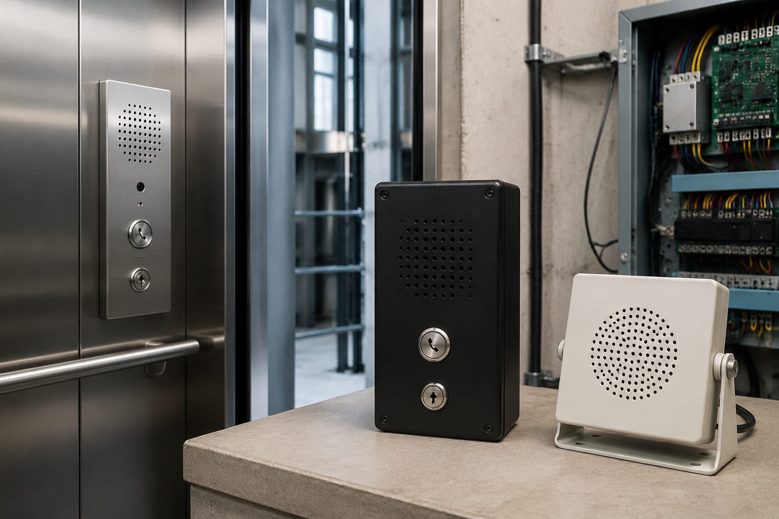
Elevator intercom systems provide a dedicated voice path between a trapped passenger in the lift car and people who can organise assistance. A dependable installation is more than a handset in the car: it needs the right station layout, compatible wiring, supervised or appropriately backed-up power, clear call routing, and repeatable testing.
For maintenance contractors and sourcing teams, the main decision is whether to retain the existing architecture or replace it with a compatible system. Record the present station count, cable cores, power input, call buttons, connectors and controller interface before selecting any elevator intercom replacement.
What an elevator intercom system does
An elevator intercom system enables two-way communication between the car and one or more external locations, commonly the machine room, a security desk, duty room or monitoring station. Its principal use is emergency communication when a passenger needs help, including during a lift stoppage or a mains failure.
Depending on the design, the system may include:
- A car operating panel (COP) microphone, speaker and alarm or call button
- An intercom handset or hands-free master station in the machine room
- A duty-room, security-desk or guard-room station
- A central power supply, amplifier or intercom controller
- Wiring through the travelling cable and fixed building riser
- Battery backup, where required by the system design
- Call indication lamps, buzzers or relay outputs for alerting staff
A standard intercom is not automatically a remote monitoring solution. Some systems only establish a local voice call between fixed stations. Others provide interfaces for an auto-dialler, GSM module, building communication network or lift monitoring platform. Confirm the actual call path instead of assuming that an intercom panel will contact a mobile number or external call centre.
The intercom should also be considered separately from the alarm bell. A bell can alert people nearby, but it does not provide a conversation with the passenger. In a reliable emergency arrangement, the alarm function and voice communication function are both checked.
Two-way and multi-station configurations
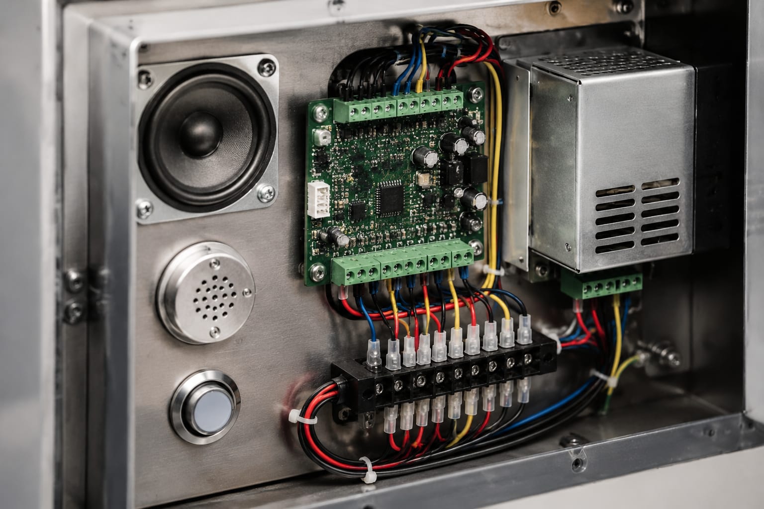
The correct configuration depends on who is expected to answer a trapped-passenger call and whether that person is continuously available. A small building may use a simple car-to-machine-room arrangement, while a residential complex, hospital, commercial tower or transport-linked property may need calls to reach a staffed duty room.
| Configuration | Typical connection | Best suited to | Key limitation |
|---|---|---|---|
| Two-way intercom | Car to machine room | Sites with trained personnel routinely near the lift equipment | Calls may go unanswered if the machine room is unattended |
| Three-station intercom | Car, machine room and duty room | Buildings with a security desk or maintenance duty point | Requires clear station priority and call-routing logic |
| Multi-car, central station | Several cars to a common monitoring point | Sites with multiple lifts and central supervision | Station identification and concurrent-call handling must be verified |
| Intercom with external communication interface | Car station connected to an interface for off-site calling | Locations where no continuously staffed on-site point is available | Network, power backup and failure behaviour require closer review |
Two-way systems
A basic two-way elevator intercom system has one station in the lift car and another in the machine room. The passenger presses the designated call button, and the receiving party answers through a handset or hands-free unit.
This configuration is straightforward, but it is appropriate only when the response location is genuinely accessible and staffed according to the building's rescue procedure. Locating the answering station inside a locked or rarely visited room can make a technically working intercom operationally ineffective.
Three-station and multi-station systems
A three-station arrangement usually adds a duty-room or security station. It can allow the car to call a regularly staffed point while retaining machine-room communication for technicians. Larger systems may connect several lift cars to a single master unit, with separate labels or indicators identifying the calling car.
Before ordering a multi-station replacement, establish:
- Which station receives the initial emergency call.
- Whether all stations can call the car, or only selected ones.
- Whether simultaneous calls are possible and how they are indicated.
- Whether the system is selective, party-line or addressable.
- Whether the duty-room station is staffed whenever lifts are operating.
- What happens if the primary answering point is unavailable.
Do not assume that adding another handset to an existing line will work. Intercom systems use different audio circuits, call-voltage arrangements, addressing methods and termination requirements.
Car, machine-room, and duty-room stations
Each station has a different operating environment and should be selected and installed accordingly.
Car station
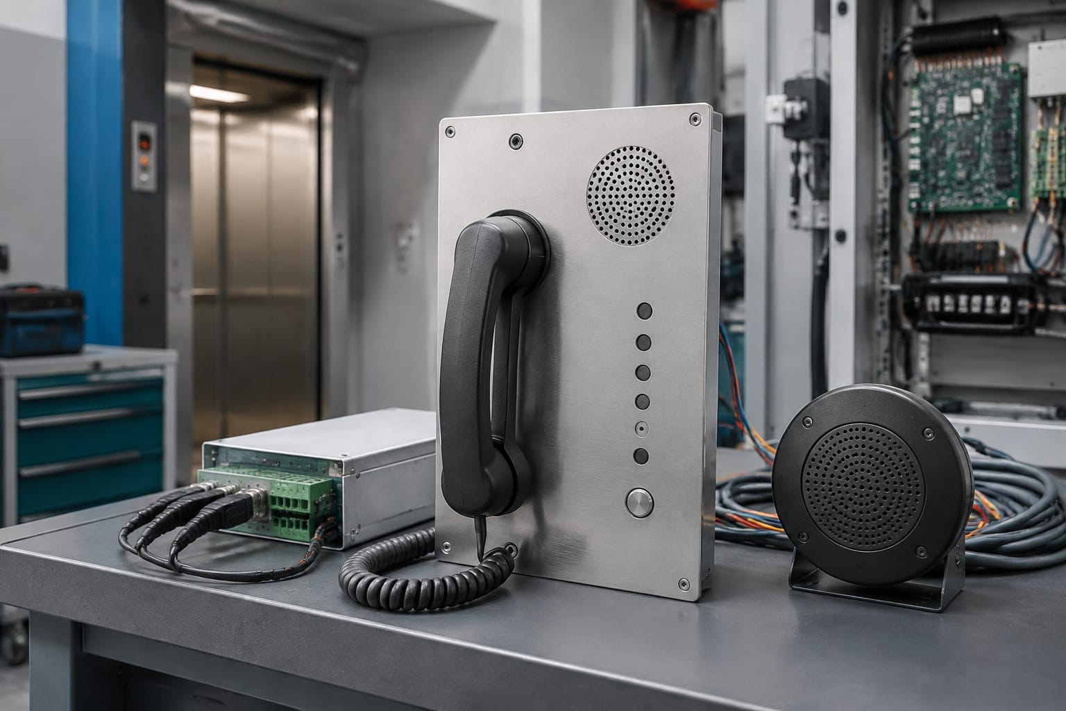
The car station is normally integrated into the COP or mounted behind a designated grille. It should give passengers an obvious means to initiate a call, with an audible indication that the call has been placed where the system supports one. Speech openings must not be obstructed by protective film, paint, dust, damaged grille mesh or a poorly aligned fascia.
Key checks for a car station include:
- Button operation and tactile condition
- Microphone and speaker direction
- Noise from fans, door equipment or vibration
- Clear labelling of the emergency communication control
- Availability of enough travelling-cable cores
- Connector security at the COP and car-top junction points
- Compatibility with the existing panel cut-out and mounting arrangement
A replacement handset or speaker panel that fits physically may still be electrically unsuitable. Check supply voltage, polarity, audio impedance where applicable, call-button contacts and connector pinout.
Machine-room station
The machine-room station is often used by technicians during maintenance and rescue operations. It may be a wall-mounted handset, desk unit or equipment-panel module. It should be positioned where the lift controller can be safely observed and operated, without creating a trip hazard from loose cords or inaccessible mounting.
The machine-room station may share space with controller equipment, but its communication function should remain clear during a fault. Confirm whether it receives power from an independent intercom supply, the lift controller, or another source.
Duty-room or security station
The duty-room station is the operational endpoint for many buildings. It should be located where a responsible person can hear and answer it promptly. A handset concealed in a back office, an unlabelled extension or a station with a muted ringer undermines the purpose of the system.
For a central station serving multiple cars, provide durable identification for each lift. The recipient should be able to identify the car or lift group before starting a response procedure. Check the facility's escalation process separately: the intercom establishes communication, while the rescue plan determines who attends and what actions are authorised.
Power supplies and backup power
Intercom power arrangements vary widely. Some systems use a dedicated low-voltage power supply, while others are integrated with a controller or emergency communication assembly. The correct supply must match the manufacturer-specified input voltage, output voltage, current capacity, AC/DC type and polarity.
Do not replace a failed supply solely by matching its physical size or nominal voltage. An unsuitable power supply can produce low audio volume, call failures, overheating, damage to electronics or intermittent operation under load.
For systems using an individual supply, source teams should confirm:
- Input supply rating and whether it is derived from normal or emergency-backed power
- Output voltage, current rating and polarity
- Number of stations and total load supported
- Battery connection, charging circuit and battery type where fitted
- Fuse type, terminal layout and enclosure dimensions
- Any status output or fault indication required by the existing installation
Where a compatible part is identified, compare the system requirements against the details of an Otis intercom dedicated power supply before treating it as a replacement. The product name alone is not enough to establish interchangeability.
Backup power is an operational requirement
Emergency communication is most needed when normal lift operation is disrupted. If the intercom relies on mains power, consider how it behaves during a building power failure, controller shutdown or rescue power transfer. A battery-backed supply, controller backup arrangement or separate emergency circuit may be used depending on the lift design.
Battery backup also needs maintenance. A battery may show normal open-circuit voltage yet fail under call load. Include backup operation in planned testing, and follow the equipment manufacturer's instructions for battery type, replacement interval and disposal.
Wiring and communication interfaces
Elevator intercom wiring usually has two main sections: a flexible route through the travelling cable to the car, and a fixed route from the shaft or machine-room junction to the receiving station. Faults can occur in either section, especially at moving cable terminations and door-zone areas.
Common wiring approaches
Older and basic systems may use dedicated analogue voice pairs with separate call and common conductors. Other systems combine audio and signalling in a proprietary cable arrangement. Newer equipment may use serial bus communication, an interface board or a dedicated emergency phone module.
Typical connections may include:
- Audio pair or pairs
- Call-button and common return
- Power positive and negative, or AC supply conductors
- Speaker and microphone conductors
- Car identification or selection lines
- Alarm, buzzer or visual-indication outputs
- Network, telephone or GSM interface connections where fitted
The terminal labels can be misleading across manufacturers. For example, COM, CALL, MIC, SPK, +, - or numbered terminals do not follow a universal wiring standard. Always use the wiring diagram for the actual unit and document each conductor before disconnection.
Travelling cable considerations
The travelling cable is a frequent source of intermittent faults because it flexes during every lift journey. Before pulling new cable through a shaft, inspect whether unused cores are available and suitable. Verify continuity from the car-top termination to the controller or machine-room termination while accounting for the car's position.
Avoid these common errors:
- Reusing unidentified cores without proving their route and continuity
- Splicing flexible travelling-cable conductors in unsuitable locations
- Running low-level audio conductors alongside high-noise power wiring without considering interference
- Leaving screen or drain-wire treatment inconsistent between ends
- Omitting strain relief at COP, car-top or junction-box entries
- Connecting a proprietary digital station to analogue wiring by terminal name alone
Communication interfaces
An intercom can connect to a telephone, GSM or monitoring interface, but this introduces further compatibility questions. Confirm whether the output is analogue telephone, dry contact, serial communication, Ethernet-based, proprietary bus or a manufacturer-specific module.
Also verify the failure mode. For example, an interface may need its own SIM, network coverage, battery support, programmed telephone numbers or periodic status checks. These are not universal properties of elevator intercom systems.
Audio and call-quality problems
Poor audio is often attributed to a faulty handset when the actual cause is wiring, power quality, acoustic feedback or station configuration. Diagnose the call path methodically before replacing parts.
| Symptom | Likely causes | Practical checks |
|---|---|---|
| No call indication | Failed call button, open conductor, missing supply, incorrect station addressing | Test button contacts, supply at each station and wiring continuity |
| One-way audio | Faulty microphone or speaker, broken conductor, loose terminal, wrong audio connection | Test each direction separately and inspect car-top and COP terminations |
| Low volume | Low supply voltage, weak amplifier, blocked grille, high-resistance connection | Measure supply under operation and inspect acoustic openings |
| Hum or noise | Poor earthing practice, interference, damaged screen, nearby power conductors | Check cable routing, shielding arrangement and termination quality |
| Feedback or whistling | Speaker and microphone coupling, excessive gain, incorrect station mode | Test with doors open and closed, then verify gain/settings where available |
| Intermittent call | Travelling cable fatigue, loose connector, vibration-related terminal fault | Test at different car positions and inspect flexing points |
Test speech in both directions using normal voice level. It is not enough for a call lamp to illuminate. Ask whether the passenger can hear instructions over fan noise and whether the receiver can understand speech from the car.
Where a car panel itself is found to be unsuitable or damaged, compare the mounting and electrical details of an elevator intercom phone assembly with the existing unit before procurement.
Replacement and upgrade planning
A good replacement decision starts with a site survey, not a catalogue image. Record the system as installed, including every component that affects compatibility.
Replacement survey checklist
Capture the following before requesting or approving a replacement:
- Lift brand, controller model and intercom make/model where identifiable
- Number and location of car, machine-room and duty-room stations
- Clear photographs of front panels, rear labels, terminals, plugs and wiring
- Input and output ratings of the power supply or controller interface
- Wiring diagram, terminal references and cable-core count
- Car-station cut-out, fixing centres, panel thickness and depth behind the COP
- Travelling-cable spare-core availability and condition
- Call routing, car identification and any existing external interface
- Battery arrangement and required operation during mains failure
- Whether the proposed part is a direct replacement, adapted replacement or full-system upgrade
Direct replacement versus upgrade
A direct replacement retains the existing wiring and station logic. It is usually the lowest-disruption option when a compatible unit is available and the wiring is sound. However, it may preserve limitations such as an unattended machine-room endpoint or poor call identification.
An upgrade may replace the master unit, car station, supply and external interface together. This is appropriate where the existing design cannot meet the building's response arrangement, has repeated faults, lacks backup capability or uses obsolete components. It requires a more complete engineering review because old wiring, panel cut-outs and controller interfaces may no longer be suitable.
For branded lift systems, a component may be part-specific rather than generally interchangeable. An intercom system phone for Hitachi elevator parts should be matched against the existing assembly's identifiers, dimensions and connections. It should not be selected on brand association alone.
Questions for B2B sourcing
Maintenance contractors, distributors and OEM buyers should obtain unambiguous answers to these points:
- Is the part intended for the exact existing model or a defined set of compatible models?
- Does it include the handset, panel, cable, mounting hardware, power supply or only one component?
- What input/output ratings and connector details apply?
- Does the system support the required number of stations and cars?
- Is rewiring, a new interface board or programming required?
- How does the system operate during a mains failure?
- What commissioning and functional tests are expected after installation?
Kelevator supplies multi-brand elevator spare parts to B2B importers, distributors, maintenance contractors and OEM buyers. When sourcing through a parts supplier, provide the survey record above so the enquiry can be assessed against the installed system rather than a generic product description.
Functional and emergency-call testing
Commissioning should demonstrate the complete emergency communication route under realistic conditions. A continuity check or a brief handset tone is not a sufficient final test.
Functional test sequence
- Check physical mounting, labelling, cable protection and terminal tightness with power isolated where appropriate.
- Restore power and verify supply voltage at the intercom equipment under normal conditions.
- Place a call from the car and confirm the intended station gives a clear audible and visual indication.
- Confirm two-way speech at normal voice level from the car to every required receiving station.
- Check that the receiving station can initiate or return a call where this is part of the design.
- Test each car separately in a multi-car installation and verify correct identification.
- Test alarm and intercom functions independently if both are installed.
- Simulate the relevant loss-of-normal-power condition in accordance with site safety procedures, then verify the documented backup behaviour.
- Record results, defects, station identifiers, battery condition where applicable and corrective actions.
During an emergency-call test, do not place a lift in an unsafe condition or carry out rescue-related actions without authorised personnel and the site's approved procedure. Lift isolation, passenger evacuation and rescue operations must be performed by competent persons.
Maintain a test record
A simple record makes recurring faults easier to identify. Note the date, lift identification, station called, responder location, audio quality in both directions, backup-power result and any corrective work. For systems connected to a phone or network interface, document the destination reached and whether the call was answered.
FAQ
Can a normal building intercom be used for a lift car?
Only if it is designed and installed to provide the required emergency communication function in that lift arrangement. Domestic or office intercom equipment may not tolerate the lift environment, support the necessary wiring, operate on backup power or provide reliable call routing.
How many cores are needed for an elevator intercom?
There is no single answer. A basic analogue arrangement may use several dedicated conductors, while proprietary or bus-based systems use different requirements. Check the actual equipment diagram and count usable travelling-cable cores before selecting a replacement.
Why does an elevator intercom work in the machine room but not at the duty room?
Likely causes include an open riser cable, failed extension station, incorrect call selection, missing power at the duty-room unit or a configuration issue. Test the car-to-machine-room path and machine-room-to-duty-room path separately to isolate the fault.
Should an intercom be upgraded when the lift controller is modernised?
It should be reviewed as part of the modernisation scope. The existing intercom may depend on controller power, legacy wiring, an obsolete interface or an impractical answering location. Retaining it can be reasonable, but only after compatibility and emergency-operation checks.
Review the installed layout and test record before choosing a like-for-like part or full upgrade. The most useful procurement specification identifies the existing equipment, wiring and emergency-call route, then states the required replacement behaviour clearly.
Related product references
For practical catalog examples related to this topic, review [Intercom System Phone Hitachi elevator parts lift accessories](/products/intercom-system-phone-hitachi-elevator-parts-lift-accessories/), [Intercom Dedicated Power Supply OTIS elevator parts lift accessories](/products/intercom-dedicated-power-supply-otis-elevator-parts-lift-accessories/), and [Intercom Phone elevator parts lift accessories](/products/intercom-phone-elevator-parts-lift-accessories/). Confirm the exact model, dimensions, ratings, and connectors before ordering.