
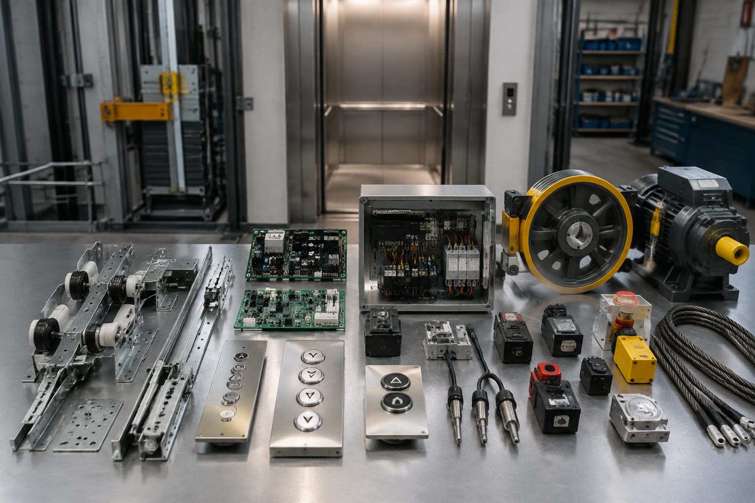
An elevator parts catalog groups replacement components by system, such as doors, controls, traction, safety and communication. To find the correct part, buyers must look beyond its general name and match the manufacturer, part number, lift model, electrical rating, connector layout, software or firmware version, dimensions and operating environment.
This guide explains 12 commonly sourced component groups and the information elevator maintenance contractors, distributors, importers, modernisation companies and OEM buyers should collect before requesting a quotation. It is a practical reference rather than a substitute for the lift manufacturer's technical documentation or assessment by a competent elevator professional.
How an elevator parts catalog is organised
Most elevator spare-parts catalogues are organised around functional systems. The exact categories vary by supplier, but a typical structure includes:
| System group | Common catalogue items | Important matching details |
|---|---|---|
| Door system | Door motors, drive boards, rollers, belts and sensors | Door operator brand, opening type, voltage and connector layout |
| Fixtures | Push buttons, COPs, LOPs, displays and indicators | Cut-out size, markings, illumination and communication interface |
| Control system | Main boards, I/O boards, relay boards and contactors | Board code, revision, firmware and supply voltage |
| Traction system | Encoders, sheaves, ropes and brake parts | Motor interface, dimensions, resolution and mechanical fit |
| Safety system | Limit switches, door contacts, light curtains and levelling sensors | Contact logic, safety function, rating and mounting |
| Emergency system | Alarm units, intercoms, batteries and auto-diallers | System compatibility, power requirement and communication method |
Catalogue families help narrow the search, but they do not establish compatibility by themselves. Two parts described as a “door motor board” may have different inputs, motor outputs, parameter settings or communication protocols. Likewise, an encoder with the correct shaft size may still provide the wrong signal type or pulse count.
Use catalogue photographs only as supporting evidence. Appearance is useful for checking mounting holes and connectors, but the label and technical data usually provide stronger identification.
Door-system components
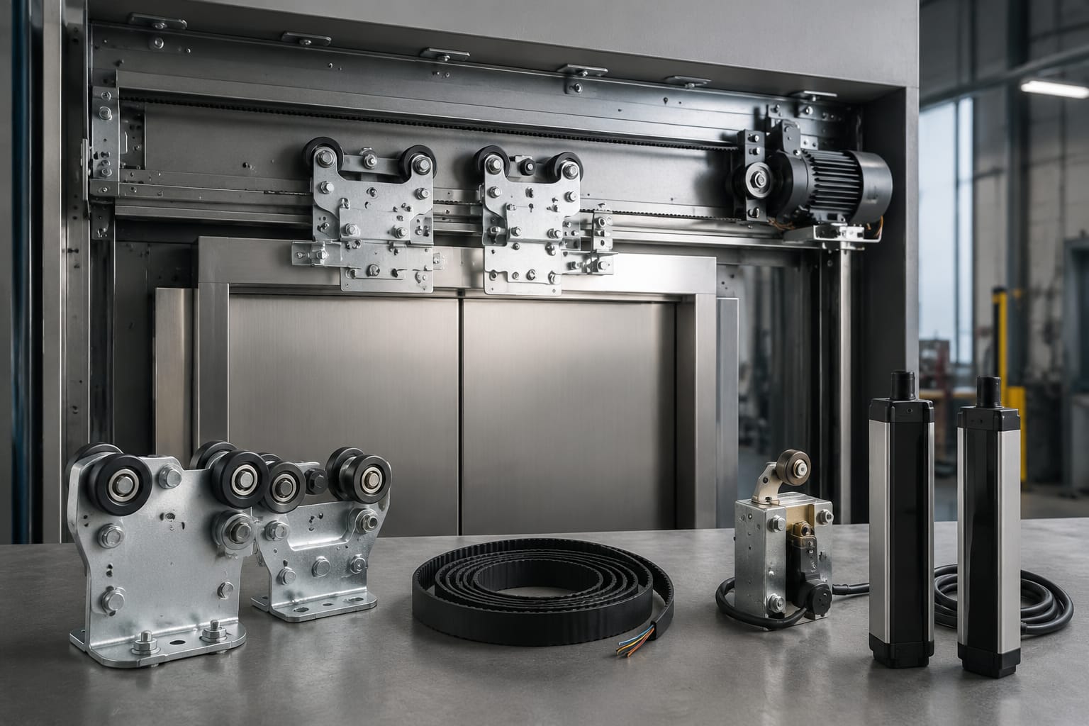
Door faults are among the most visible lift problems because they can prevent normal operation even when the controller and traction system are functional. Door components must suit the operator mechanism, opening arrangement, panel weight and control interface.
1. Door motor and door operator
The door motor provides the movement needed to open and close the car doors. It normally forms part of a wider operator assembly that may include a belt, pulley, linkage, controller and position feedback device.
For an accurate match, identify:
- Door operator manufacturer and model
- Motor label code and rated voltage
- AC, DC, permanent-magnet or other motor type
- Rated current and power, where marked
- Shaft dimensions and mounting arrangement
- Connector type and wire sequence
- Centre-opening or side-opening door arrangement
- Any encoder or position sensor used with the motor
Do not select a motor based only on physical size. Its torque characteristics, feedback arrangement and compatibility with the door controller can affect acceleration, closing force and positioning.
2. Door motor control board
A door motor board controls opening and closing sequences, speed profiles, motor direction and obstruction response. Depending on the design, it may operate as a stand-alone door controller or communicate with the main lift controller.
Record the complete board number, revision code, software label and operator model. Check the number and position of connectors, since boards from the same product family can have similar housings but different pin assignments.
A listing such as this [Hitachi elevator door motor board](/products/door-motor-board-hitachi-elevator-parts-lift-accessories/) illustrates the type of product category buyers may encounter. Compatibility still needs to be established from the installed board details and lift documentation; a brand reference alone is insufficient.
3. Door rollers, belts and mechanical guides
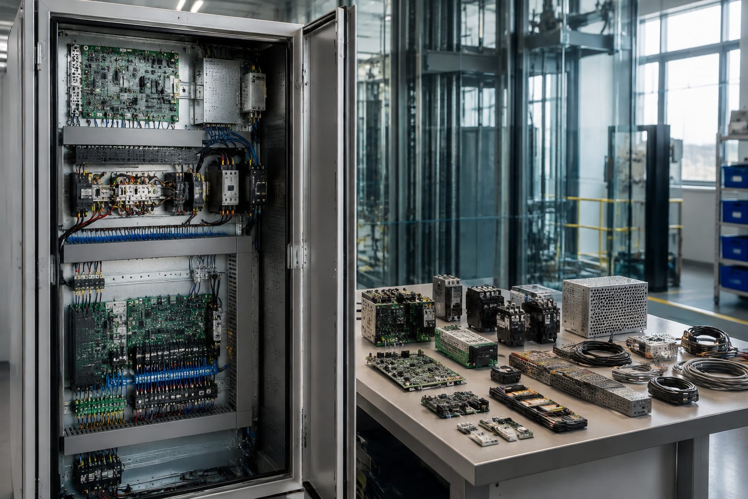
Rollers, hanger wheels, timing belts, guide shoes and related hardware transfer door movement while keeping the panels aligned. Worn components may contribute to noise, vibration, uneven movement or unreliable closing.
Measure or confirm:
- Roller diameter, width and bearing bore
- Belt pitch, tooth profile, length and width
- Bracket dimensions and hole centres
- Guide-shoe profile
- Door-panel arrangement
- Material or hardness specification, where required
For belts and rollers, approximate measurements can result in poor tension or alignment. Use a calliper where appropriate and record dimensions in millimetres.
Buttons, panels, and displays
Fixtures are both functional and visible. A replacement must fit the panel and work with the lift's wiring or serial communication system while preserving clear, suitable markings.
4. Push buttons and button modules
Elevator push buttons may be individual mechanical units, illuminated modules or intelligent devices connected through a serial network. Catalogues may separate them into car operating panel buttons, landing call buttons, alarm buttons and door-control buttons.
Check:
- Faceplate shape and dimensions
- Panel cut-out and fixing method
- Contact arrangement, such as normally open or normally closed
- Illumination voltage and colour
- Connector or terminal style
- Symbol, floor marking and tactile requirement
- Whether the button includes a PCB or communication module
A button that fits the aperture may still be electrically incompatible. In particular, do not connect an illumination circuit until its voltage and polarity have been confirmed.
5. Car and landing operating panels
The car operating panel (COP) contains floor-selection and operational controls inside the lift. Landing operating panels (LOPs) contain call buttons and may incorporate position or direction indicators.
Complete panels are usually configuration-specific. A sourcing request should include the number of floors served, button layout, panel dimensions, fixing method, finish, key-switch positions, display opening and communication arrangement. For modernisation work, also specify whether the requirement is for a complete panel, a faceplate or only internal modules.
Visible finish descriptions such as “stainless steel” are not precise enough where appearance must match an existing installation. Confirm the grade or finish reference, grain direction and surface treatment where these are important.
6. Floor displays and direction indicators
Displays communicate floor position, travel direction, service status and fault messages. Common types include segmented LED displays, dot-matrix modules, LCD units and integrated multimedia indicators.
Matching criteria include:
- Display board part number and revision
- Physical dimensions and viewing orientation
- Supply voltage
- Serial, parallel, CAN or proprietary interface
- Character set and floor designations
- Connector pinout
- Controller protocol and software compatibility
Displays that use the same communication technology are not automatically interchangeable. The message format may be proprietary, and a replacement may require configuration through the controller or display board.
Controllers, boards, and relays
Electronic control parts require particularly careful identification. Hardware revisions, parameter files and firmware can change while the catalogue description remains broadly the same.
7. Main controller and I/O boards
The main controller processes calls, monitors the safety circuit and coordinates doors, drive commands and floor positioning. Input/output boards extend connections for landing signals, switches, indicators and other field devices.
Before sourcing a board, record:
- Manufacturer and complete assembly number
- PCB code, revision and date code
- Firmware or EPROM label
- Lift controller model
- Supply and signal voltages
- All connector identifiers
- Number of floors and relevant configuration
- Whether parameter transfer or programming is required
Replacing a board can involve more than installing hardware. Stored parameters may contain floor data, door timings, drive settings or site-specific inputs. Confirm whether configuration can be transferred and whether commissioning tools are required.
8. Relay boards, relays and contactors
Relay boards switch multiple control circuits through a packaged PCB assembly. Individual relays and contactors may operate brakes, door circuits, fans or auxiliary equipment, depending on the control design.
For a board-level replacement, compare the complete board code, revision and connector positions. The [Mitsubishi elevator relay board category](/products/relay-board-mitsubishi-elevator-parts-lift-accessories/) is an example of the catalogue terminology used for this component group.
For an individual relay or contactor, check:
- Coil voltage and whether it is AC or DC
- Contact configuration
- Contact current and utilisation category
- Number of poles
- Terminal layout and mounting method
- Auxiliary contacts
- Suppression device, if fitted
A relay that physically plugs into the same socket may have a different coil voltage or contact arrangement. Treat the printed electrical markings as essential matching information.
Traction and motion components
Traction components transfer and monitor lift movement. Their selection affects mechanical fit, feedback accuracy and compatibility with the drive and controller.
9. Traction encoder
An encoder reports motor position, speed or direction to the drive and control system. It may be mounted on the motor shaft, incorporated into the machine or connected through a coupling.
When reviewing a [traction encoder for elevator applications](/products/traction-encoder-elevator-spare-parts/), compare the installed unit's full technical data rather than relying on the general product name. Relevant details include:
- Encoder manufacturer and model
- Incremental or absolute feedback type
- Pulses per revolution or resolution
- Output circuit and signal channels
- Supply voltage
- Shaft type and diameter
- Flange and mounting dimensions
- Cable length, connector and pinout
- Required communication protocol
Incorrect encoder feedback can prevent normal drive operation or produce inaccurate speed information. Installation and calibration should follow the machine and drive manufacturer's procedure.
10. Traction sheaves, ropes and brake components
Traction sheaves transmit motion through suspension ropes or belts, while the machine brake holds the car when required. These are safety-critical mechanical components and should not be chosen from a photograph or broad dimensional estimate.
For sheaves, document the outside diameter, number of grooves, groove profile, groove pitch, bore, keyway and machine model. For ropes or coated suspension media, confirm the specified construction, diameter, quantity and termination arrangement from the applicable lift documentation.
Brake sourcing may involve a complete brake assembly, coil, lining, armature, spring or switch. Record the machine model, component code, coil voltage, dimensions and manufacturer-defined adjustment requirements. Any substitution needs engineering validation for the specific lift system.
Sensors and safety devices
Sensors provide position and condition information, while safety devices interrupt or prevent unsafe movement. Similar-looking switches can perform very different duties, so the circuit function must be understood before replacement.
11. Levelling sensors, limit switches and door protection
Levelling sensors help the controller stop the car accurately at a landing. Limit switches identify defined travel or mechanism positions. Door protection may use light curtains, photocells, safety edges or mechanical contacts to detect an obstruction.
Identify the device by both construction and function:
- Sensor technology, such as magnetic, optical or inductive
- Sensing distance or operating position
- Supply voltage
- PNP, NPN, relay or dry-contact output
- Normally open or normally closed logic
- Cable and connector arrangement
- Mounting dimensions
- Environmental protection requirement
- Associated magnet, vane, reflector or transmitter
A generic proximity sensor is not necessarily suitable for an elevator levelling circuit. Signal logic, response behaviour and environmental resistance must correspond with the original design.
Safety-circuit components, including door locks, final limit switches and overspeed-related devices, require additional care. Confirm the exact approved component for the lift design and follow applicable installation, inspection and testing procedures. Do not bypass a safety contact to accommodate an incompatible part.
Communication and emergency parts
Emergency communication components must remain functional during the conditions for which they are intended. Their operation can depend on the building's communication service, controller interface and backup supply.
12. Alarm units, intercoms and emergency power modules
This category includes alarm bells or buzzers, car-to-control-room intercoms, auto-diallers, emergency telephones, backup batteries and emergency lighting modules. Some systems are stand-alone, while others are integrated into the COP or lift controller.
Confirm:
- Device manufacturer and model
- Supply voltage and current requirement
- Communication medium and interface
- Number of communication points
- Wiring arrangement and connector type
- Battery chemistry, voltage, capacity and dimensions
- Charger compatibility
- Required configuration or programming
- Integration with alarm buttons and monitoring outputs
A replacement battery should not be selected only by nominal voltage. Terminal style, physical size, chemistry, charging method and capacity must also suit the system. After replacement, the complete alarm, communication and backup operation should be functionally tested under the required operating conditions.
How to identify an exact catalog match
An accurate sourcing request reduces unnecessary exchanges and helps suppliers distinguish between visually similar variants. Build the request from evidence taken from the installed equipment and technical records.
Follow a structured identification process
- Define the failed function. State what the lift is doing and how the fault was diagnosed. Avoid assuming that the most visible component is necessarily defective.
- Identify the system and component. Note whether the part belongs to the door operator, controller, fixture, traction machine, safety circuit or emergency system.
- Photograph every label. Take clear, straight photographs of the complete part, manufacturer label, PCB markings, connectors and installed orientation. Do not remove labels for a cleaner photograph.
- Transcribe the codes. Type the part number, serial number, revision, firmware code and electrical ratings into the enquiry. Photographs alone can be difficult to search and may hide ambiguous characters.
- Record the lift context. Provide the lift manufacturer, controller or machine model, door operator model, number of stops and approximate installation or modernisation period where known.
- Measure mechanical details. Include overall dimensions, shaft diameter, hole centres, belt profile or panel cut-out as relevant. State the unit of measurement.
- Confirm electrical details. Record voltage, current, frequency, contact logic, output type and connector pinout where applicable.
- Check software dependence. Ask whether the board or display needs programming, parameter transfer, firmware matching or a commissioning tool.
- Separate mandatory and flexible details. Part number, electrical compatibility and safety function are usually mandatory. Cosmetic finish may be flexible in some back-of-house applications but critical for visible fixtures.
- Compare the quotation line by line. Before ordering, verify the offered manufacturer, part code, revision, included accessories and configuration against the request.
Common catalogue matching mistakes
- Ordering by component name without a part number
- Assuming all parts from one lift brand are interchangeable
- Matching a PCB by colour or connector count alone
- Ignoring suffixes and revision letters
- Confusing input voltage with output voltage
- Treating a similar connector as proof of an identical pinout
- Omitting the door operator, controller or machine model
- Reusing old photographs after a previous modernisation
- Assuming a replacement board includes software or parameters
- Substituting a safety device without engineering confirmation
Where the original part is obsolete, an alternative may involve an adaptor, wiring change, parameter update or complete subsystem replacement. Such a proposal should state what changes are needed, which existing components remain compatible and how the modified system will be tested.
Kelelevator supplies multi-brand elevator spare parts to B2B importers, distributors, maintenance contractors and OEM buyers. Whether requesting a part from Kelevator or another supplier, begin with the full identification record: part and revision codes, lift-system details, ratings, dimensions, connector photographs and required quantity. This gives the sourcing team enough information to check a catalogue match without relying on assumptions.