
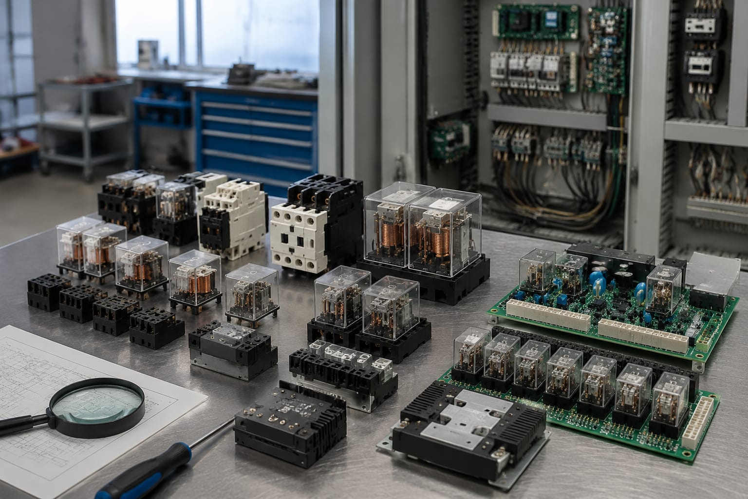
An elevator relay is an electrically operated switching component that allows a lift controller to control higher-load or separate circuits safely. Depending on its position in the system, it may operate door functions, safety-chain logic, levelling signals, car-top controls, indicators or interface outputs.
A failed relay can cause intermittent lift stoppages, doors that do not respond, incorrect fault indications or a controller that will not permit a run. However, a relay should not be replaced on symptoms alone. The supply voltage, control command, connected load, socket or board condition, and exact relay or board revision must be checked first.
What elevator relays control
Elevator relays isolate and switch control signals between parts of the lift system. In an older relay-based controller, individual relays may handle many logic functions. In modern microprocessor controllers, relay outputs are commonly used as the final switching stage between the controller board and field devices.
Typical elevator relay applications include:
- Door control: energising door open, door close, nudging or door lock-related circuits.
- Safety-chain monitoring: passing status through circuits involving landing-door interlocks, car-door contacts, pit switches, top-of-car inspection switches and emergency stop devices.
- Motor and brake control interfaces: operating contactor coils or providing permissive signals. These are critical circuits and must be assessed as part of the complete control design.
- Car-top functions: supporting inspection, stop, travel and communication-related functions on the car roof.
- Landing and car signals: switching inputs or outputs for call registration, indicators, buzzers and other auxiliary equipment.
- Interface circuits: connecting controller logic to devices that use a different voltage level or require electrical separation.
- Fire, access and special-operation interfaces: passing approved control signals between the lift controller and external systems.
A relay is only one component in its circuit. For example, a door relay may appear to be faulty because a door lock contact is open, an input voltage is missing, a controller output is inhibited, or the door operator has drawn excessive current. Establishing the relay's actual job is the first step in diagnosis.
Electromechanical and solid-state relays
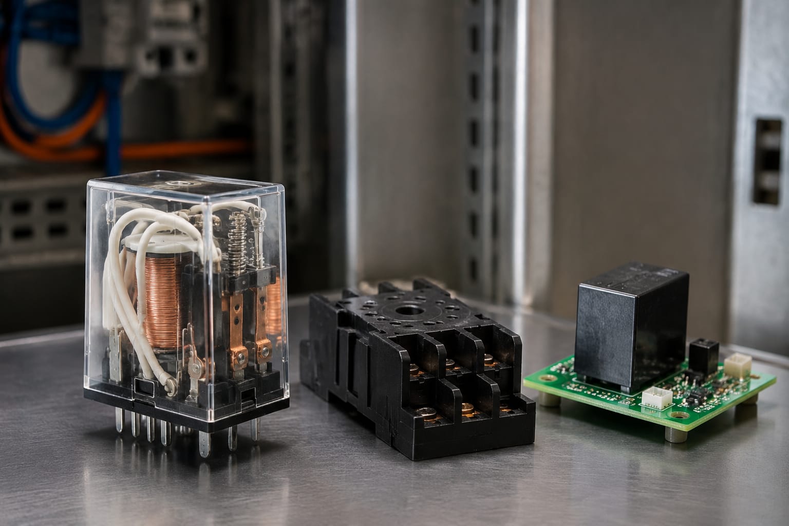
The two main categories are electromechanical relays (EMRs) and solid-state relays (SSRs). They perform a similar switching role but operate differently and are not automatically interchangeable.
| Feature | Electromechanical relay | Solid-state relay |
|---|---|---|
| Switching method | Physical moving contacts | Semiconductor switching device |
| Coil or input | Energised coil moves an armature | Low-power control input activates electronic switching |
| Audible operation | Usually produces a click | Silent |
| Contact behaviour | Can switch AC or DC, depending on design | Usually specified for a particular load type and switching method |
| Isolation | Mechanical contact separation when open | Electronic output may have leakage current |
| Typical concern | Contact wear, coil failure, sticking or chatter | Heat dissipation, leakage, unsuitable load type or surge damage |
| Replacement rule | Match coil, contacts, mounting and approvals | Confirm load type, current, voltage, leakage and thermal requirements |
Electromechanical relays in lift controllers
Electromechanical relays remain widely used in elevator equipment because they provide clear contact states, reliable isolation and straightforward fault finding. They may be plug-in relays mounted on sockets, PCB-mounted relays fitted to a board, or enclosed relays within a dedicated module.
Common contact arrangements include:
- SPST-NO: one normally open contact.
- SPST-NC: one normally closed contact.
- SPDT/changeover: one common terminal switches between normally closed and normally open contacts.
- DPDT or multi-pole changeover: multiple isolated changeover contacts operated by one coil.
The contact configuration matters as much as the coil voltage. A relay with the correct coil rating but the wrong terminal arrangement can create an unsafe or non-functional circuit.
Solid-state relays and electronic outputs
Solid-state relays are used where rapid cycling, silent operation or long switching life is needed. Some elevator equipment also uses transistor, triac or opto-isolated output stages that may be described informally as relay outputs even though they do not contain a conventional relay.
Do not substitute an SSR for an electromechanical relay simply because voltage and current figures look similar. An SSR may not switch DC in the same manner, may remain partially conductive when off, or may need a heat sink. Conversely, a mechanical relay may be unsuitable where the original electronic output has specific switching-speed or monitoring requirements.
Use the component type specified by the controller, door operator or original equipment documentation.
Relay boards in door and safety circuits
A relay board groups several relays and related components on one PCB. It may include sockets, fuses, LEDs, suppression diodes, optocouplers, resistors, connectors and protective circuitry. These boards are common in door control, car-top, safety and interface applications.
The board must be treated as an assembly, not just as a collection of replaceable relays. A burnt track, damaged connector pin, failed suppression component or water-contaminated PCB can produce the same symptoms as a faulty relay.
In door systems, a relay board can distribute commands between the controller and door operator while monitoring interlocks and door-zone conditions. A failed output may leave doors open, prevent closing, cause repeated door reopening or stop the lift from receiving a valid door-lock signal. Before condemning the board, check the mechanical door operation, lock contacts, wiring, controller command and supply at the board.
For equipment where the part identification matches the installed assembly, review the connector layout and circuit role of a [door bypass control relay board for Otis lift applications](/products/door-bypass-control-relay-board-otis-elevator-parts-lift-accessories/). The application name alone is not enough to establish compatibility.
Car-top relay boards can support inspection and control functions at the top of the car. They deserve particular care because the car-top environment includes moving-travelling-cable connections, inspection controls and safety-related wiring. A [KCE/KONE car-top relay board](/products/elevator-car-top-relay-board-kce-kone-lift-parts/) should be matched against the actual board number, revision and connector arrangement before sourcing.
Safety circuits require a higher standard of checking
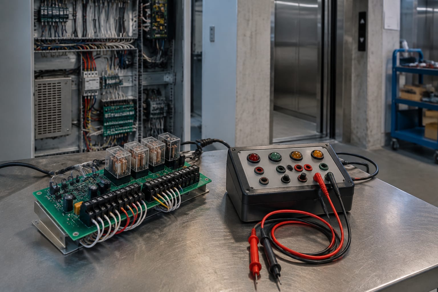
The elevator safety chain is designed so that an open or invalid safety condition stops normal operation. Relays associated with safety monitoring may be safety-rated components, part of a monitored circuit, or conventional components used alongside a dedicated safety architecture. Their function cannot be inferred only from their location.
Never bypass a safety contact, bridge relay terminals or substitute a differently rated component to restore service temporarily. Such actions can hide the underlying fault and defeat intended protections. Work on safety circuits should be performed only by trained lift personnel using the applicable controller documentation and site safety procedures.
Common signs of relay failure
Relay failure may be permanent, intermittent or load-dependent. The following signs are useful starting points, but none proves that the relay itself is at fault.
| Symptom | Possible relay-related cause | Other checks needed |
|---|---|---|
| Lift does not start | Coil is open, relay is not energising, contacts have failed open | Safety chain, controller fault status, supply voltage, contactor circuit |
| Door will not close or reopen repeatedly | Door relay contacts are worn or relay command is unstable | Door locks, light curtain, door operator, mechanical resistance, inputs |
| Relay clicks but output does not operate | Contacts are burnt, high-resistance or connected load circuit is open | Measure output voltage under load, inspect terminals and wiring |
| Relay does not click | Missing coil voltage, failed coil, failed controller output | Coil command, common supply, output fuse, connector condition |
| Intermittent stopping or erratic operation | Contact chatter, loose socket, cracked solder joint, failing coil | Vibration, temperature, terminal tightness, board condition |
| Burnt smell or discolouration | Overheated contacts, overloaded circuit or PCB damage | Load current, terminal heat, wiring size, downstream fault |
| Repeated fuse failure | Shorted coil, damaged suppression diode or board fault | Isolate load and follow the manufacturer's diagnostic process |
| Relay remains energised or output stays on | Welded contacts, stuck armature or external backfeed | Coil command, wiring cross-feed, controller output state |
Symptoms that point to the circuit, not the relay
A relay is often blamed because it is visible and clicks during a fault. A clicking relay only confirms that its coil is receiving some form of energisation. It does not prove that the contacts are healthy, that the controller command is correct, or that the downstream device can operate.
Common non-relay causes include:
- A weak or missing 24 V DC control supply.
- A loose terminal or corroded connector pin.
- A failed door lock, limit switch or sensor.
- A defective contactor, brake rectifier, solenoid or door motor.
- Damaged travelling cable conductors.
- An input held in an invalid state by a mechanical fault.
- Incorrect parameter settings or a controller fault condition.
Intermittent faults require special care. Replacing a relay may appear to solve the issue temporarily because connectors are disturbed during the work. Inspect socket tension, solder joints, cable strain and heat-related behaviour before concluding that the old relay was the root cause.
Check coil voltage and contact ratings
A replacement elevator relay must match the electrical and mechanical requirements of the original circuit. Its appearance, pin count or manufacturer series does not establish suitability.
Coil voltage and coil type
Start with the marking on the existing relay, schematic or board documentation. Common control coil voltages include 24 V DC, 48 V DC, 110 V AC and 230 V AC, but the actual value depends on the controller design.
Confirm:
- Rated coil voltage: for example, 24 V DC rather than 24 V AC.
- AC or DC coil type: these are not interchangeable.
- Polarity: some DC relays with LEDs, diodes or electronic suppression require correct polarity.
- Coil power or resistance: relevant where the board output has a limited drive capacity.
- Pick-up and drop-out behaviour: important in monitored or low-voltage control circuits.
A DC relay fitted with a flyback diode may damage a circuit or fail to energise if it is installed with reversed polarity. A replacement also needs to suit any external suppression already fitted across the coil.
Contact rating is more than one ampere figure
Contact markings may state a current rating at a particular voltage and load type. That figure should be read with the datasheet and circuit duty in mind.
Check all of the following:
- Switching voltage: AC and DC ratings are often different.
- Continuous current and inrush current: motors, solenoids and contactor coils can have a higher starting current.
- Load type: resistive, inductive, motor or electronic loads impose different contact stress.
- Number and configuration of contacts: NO, NC and changeover requirements must match the circuit.
- Minimum load: some contacts are unsuitable for very low-level signal switching after use on power loads.
- Electrical endurance: relevant for frequently operated door and signalling circuits.
- Contact material and approved use: especially where the original design specifies a particular relay family.
Do not increase a fuse size or fit a higher-current relay as a response to contact burning without finding the cause. Overcurrent can arise from a failing load, incorrect wiring, a shorted suppressor or loose terminations producing heat.
Diagnose the circuit before replacement
A structured diagnosis reduces unnecessary part replacement and helps prevent repeat failures. Isolate the lift and follow the site lockout, controller and safe-working procedures before handling live circuits. Measurements should be carried out only by competent personnel using suitable instruments and methods.
Practical relay diagnostic sequence
- Record the fault condition. Note the controller display, relay identifier, operating mode, door position and any repeatable trigger. Intermittent faults are easier to investigate when the conditions are documented.
- Verify the supply. Check the relevant control supply and fuse condition. Measure at the relay socket or board connection, not only at the power supply.
- Confirm the command to the coil. With the circuit in its correct operating state, determine whether the controller is asking the relay to energise.
- Check the coil. With power isolated as required, compare coil resistance against the expected component information. An open circuit or clearly abnormal reading indicates a problem, but resistance alone does not prove performance under operating voltage.
- Check contact state and voltage drop. Test whether contacts change state correctly and whether they pass voltage under the actual load. A relay can show continuity on a meter yet fail under load because of high contact resistance.
- Inspect the socket, board and terminals. Look for heat marks, loose contact grips, cracked solder joints, damaged tracks, moisture and connector damage.
- Test the connected device and wiring. A door operator, solenoid or contactor with a fault can overload the relay or prevent the expected outcome even when the relay is sound.
- Review the controller logic. Ensure safety inputs, mode selection and programme conditions permit the output to operate.
Avoid probing a live PCB in a way that can short adjacent pins. Use correct test points, insulated probes and the equipment documentation. For a board with multiple interconnections, a wiring diagram is generally more valuable than trial replacement.
Match boards, connectors, and revisions
When the relay is board-mounted or the relay board itself must be replaced, part matching becomes more demanding. A similar-looking board can have different firmware support, connector pinouts, relay contact arrangements or component populations.
Use this checklist before ordering:
- Original manufacturer part number and any suffix.
- Board reference number printed on the PCB.
- Hardware revision, issue or version marking.
- Controller, door operator or lift-system model.
- Number, position and keying of connectors.
- Connector pin labels and cable orientation.
- Relay coil and contact markings where visible.
- Power supply voltage and input/output functions.
- Mounting holes, dimensions and enclosure clearance.
- Whether jumpers, DIP switches or configuration links are present.
- Any visible modifications made during a previous repair.
A board revision may change without changing the basic function, but that must be confirmed through manufacturer documentation or an authorised technical source. Never assume a newer issue is backward-compatible, and do not transfer jumpers or settings without recording the original arrangement.
An [elevator interface relay board](/products/interface-board-relay-board-lift-parts-elevator-accessories/) is relevant where a controller uses a dedicated relay interface. Confirm the specific application and connection details before selecting it, because interface boards can differ substantially between controller families.
Common board replacement mistakes
The most frequent avoidable errors are:
- Ordering by photograph only.
- Matching a generic relay number while ignoring the PCB number.
- Reversing connectors that are physically similar.
- Moving a relay to a different socket without checking the coil and contact designation.
- Reusing heat-damaged terminals or loose sockets.
- Failing to identify why the original board or relay overheated.
- Powering up before rechecking all safety-chain and door-circuit connections.
- Ignoring configuration settings, jumpers or revision requirements.
For B2B sourcing, provide clear photographs of both sides of the board, all labels, connectors and the relay markings alongside the exact controller or door-equipment details. This gives a distributor or parts supplier the information needed to assess a match rather than relying on a product name alone. Kelevator supplies multi-brand elevator spare parts for B2B importers, distributors, maintenance contractors and OEM buyers, so accurate identification information is particularly useful when seeking an equivalent or replacement assembly.
Test the system after replacement
Replacement is not complete when the relay clicks or the controller powers up. The circuit and lift must be tested in the relevant normal and service modes using the equipment manufacturer's procedures.
After installing a relay or relay board:
- Confirm the replacement part is seated correctly and all connectors are fully engaged.
- Recheck terminal tightness, relay orientation, fuse rating and cable routing.
- Restore power in accordance with the controller procedure and check for immediate faults, overheating or abnormal sounds.
- Verify the intended function under controlled conditions, such as the relevant door command, car-top function or interface output.
- Confirm the output de-energises when it should, including when the controlling signal is removed.
- Test related functions that could be affected by the same circuit.
- Check door operation, levelling, landing calls and safety-related responses as applicable to the repair scope.
- Review fault logs and record the component number, board revision, reason for replacement and test results.
Do not leave a lift in service if safety functions, door locking or normal operation have not been restored and verified. Where a replacement is followed by repeated relay heating, chatter or fuse operation, return to diagnosis. The fault may be a downstream load, incorrect part selection, poor connection or control-board issue rather than a defective new relay.
Frequently asked questions
Can an elevator relay be repaired instead of replaced?
Some faults originate in the socket, solder joint, connector or board track rather than the relay itself. A plug-in relay can sometimes be replaced individually where the design permits. Opening or attempting to repair a sealed relay is generally not appropriate for lift control work, particularly where reliable contact performance is required. Replace it with a correctly specified part and investigate the cause of failure.
Can I use a relay with a higher contact current rating?
Only if every relevant requirement also matches: coil voltage, contact layout, pin arrangement, load type, physical fit, board drive capability and the equipment design. A higher current number alone does not make a relay compatible.
Why does an elevator relay click but the lift still does not run?
The coil may be energising while the contacts are worn, the output wiring is open, a downstream component has failed, or another safety or controller condition is preventing travel. Check the complete circuit and the controller's fault status.
Are relay boards interchangeable between similar lift controllers?
Usually, this should not be assumed. Similar controllers can use different connectors, pin assignments, revisions or software expectations. Match the exact board identification and verify compatibility before installation.
Correct relay selection begins with the circuit function and ends with a recorded operational test. When sourcing a relay or board, share the original part number, controller details, voltage markings, photographs and board revision so the replacement can be assessed against the actual installation.