
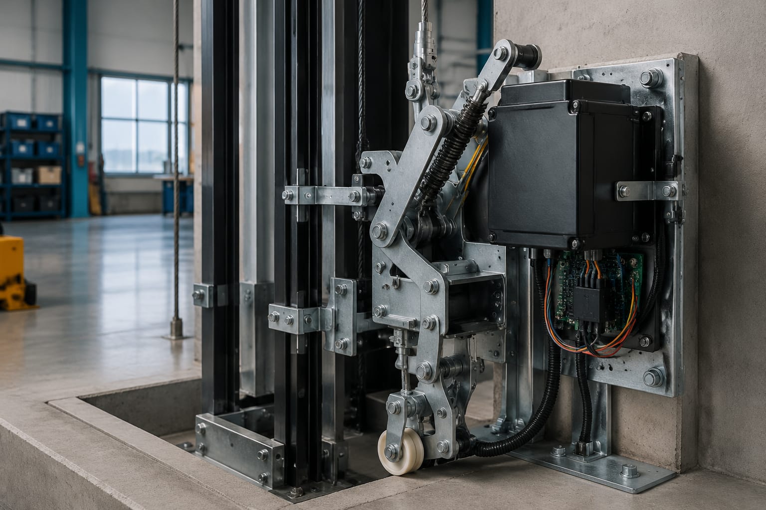
Lift safety gear is the mechanical device that grips the guide rails and arrests an elevator car, or in some designs a counterweight, if an overspeed condition or specified safety event occurs. It works as part of a system: the overspeed governor detects excessive speed, the governor rope and linkage actuate the safety gear, and the jaws clamp onto the rails.
For maintenance and sourcing teams, the key rule is simple: never select, adjust or replace lift safety gear by appearance alone. Its compatibility depends on the car design, rated speed, rated load, guide rail profile, governor arrangement, linkage travel and the approved safety arrangement for that lift.
How elevator safety gear stops the car
A lift safety gear is mounted on the car frame, usually near the lower part of the sling. When actuated, gripping elements engage both car guide rails. The resulting braking force is transferred through the car frame into the rails and the building structure.
In a typical governor-operated event, the process is as follows:
- The elevator car exceeds the governor's tripping speed.
- The overspeed governor locks its rope.
- Continued car movement pulls the governor rope relative to the car.
- The rope movement operates a linkage, lever or safety mechanism on the car frame.
- The safety gear grips the guide rails and decelerates the car to a stop.
The exact sequence, operating clearances and reset method vary by lift design. Some safety arrangements also use electrical contacts to remove drive power before or during mechanical engagement. Electrical isolation is important, but it does not replace the mechanical stopping function of the safety gear.
Safety gear is intended for abnormal conditions, not normal stopping. A car that repeatedly stops through safety-gear operation needs investigation before it is returned to service. Repeated actuation can damage rail faces, alter clearances, deform linkage components or create an uneven gripping condition.
Governor, rope, linkage, and safety gear
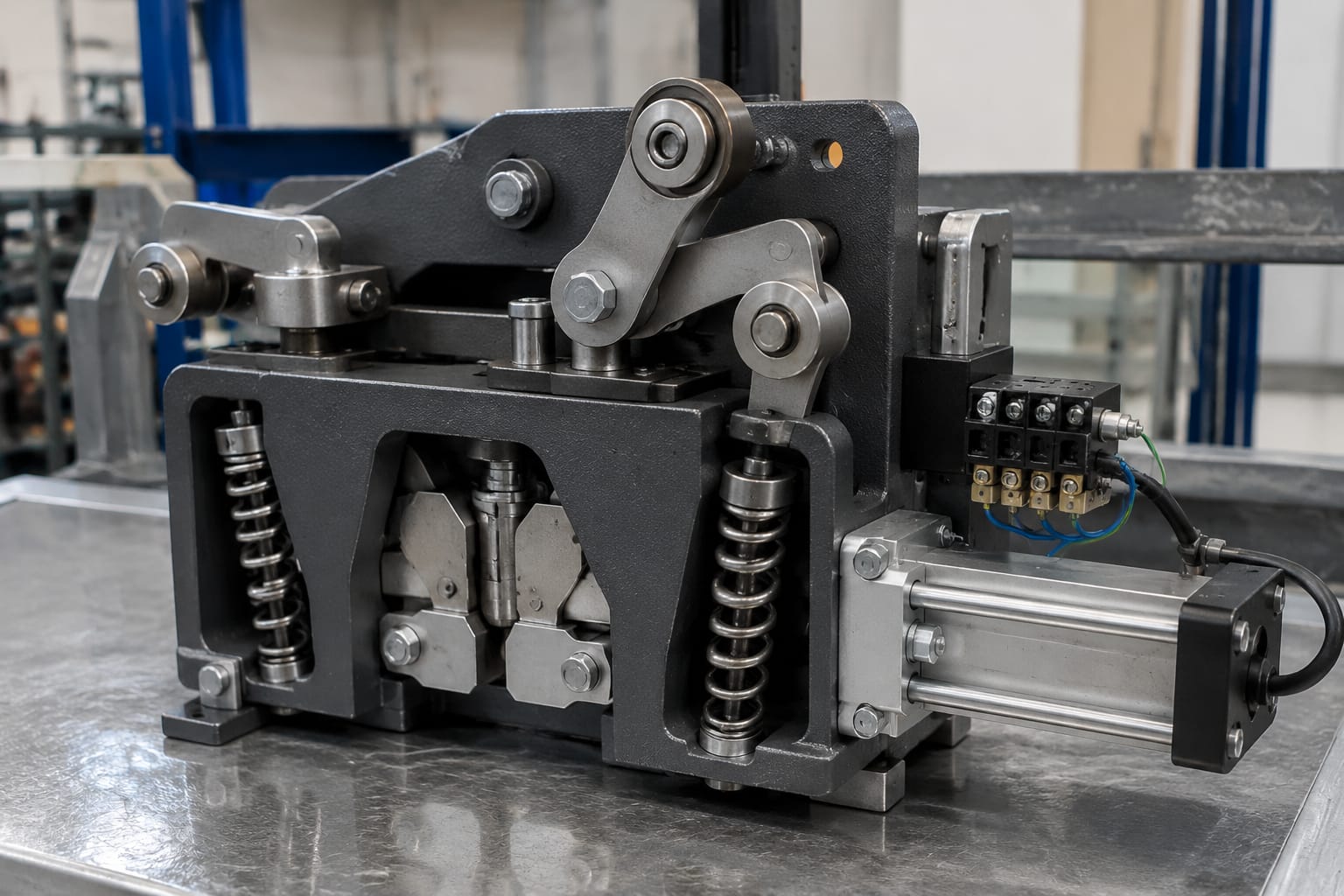
The safety gear cannot be assessed as an isolated spare part. A reliable inspection considers the whole operating chain.
Overspeed governor
The governor is the speed-sensing device. Its trip setting must match the lift's design requirements. A governor that trips too late may not provide the intended protection; one that trips too early can cause nuisance operation and unnecessary shutdowns.
Confirm the governor make, model, pulley diameter where relevant, rope specification, direction of travel arrangement and trip characteristics before replacing associated components. Do not assume that a similar-looking governor is interchangeable.
Governor rope and tension system
The governor rope transmits movement from the governor to the car safety mechanism. Wear, corrosion, poor tension, contamination, incorrect routing or an unsuitable rope diameter can affect operation.
During maintenance, examine:
- Rope condition, broken wires and visible corrosion
- Rope tension and the condition of the tension pulley arrangement
- Rope terminations, clamps and fixing points
- Alignment through the governor and tension pulley
- Clearance from guards, brackets and moving components
- Any sign of rope slip, polishing, flattening or contamination
A rope may look serviceable while still being unsuitable for the installed governor if its construction or diameter differs from the approved specification.
Mechanical linkage
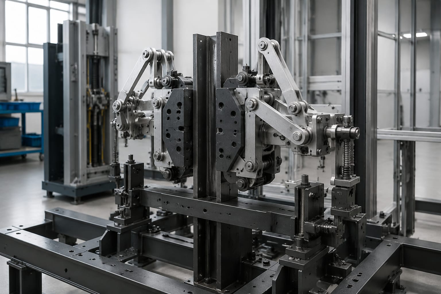
Linkage converts rope movement into a controlled movement at the safety gear. It may include rods, levers, shafts, pins, springs and actuating cams. Bent rods, seized pivots, improvised fasteners and unequal left-right travel are frequent reasons for unreliable engagement.
The linkage must operate both sides of the safety gear as intended. A mechanism that engages one rail before the other can produce uneven forces, rail damage or a car frame distortion risk. Never compensate for a sticking mechanism by increasing spring force or altering an adjustment without the relevant technical procedure.
Electrical monitoring
Safety-gear and governor arrangements commonly include electrical contacts to supervise the system and prevent normal operation after a trip. Wiring, contacts, mounting and the safety circuit should be checked as part of fault diagnosis.
For related electrical monitoring components, review the application details before selecting a [brake micro-movement detection switch for lift systems](/products/brake-micro-movement-detection-switch-lift-parts-elevator-accessories/) or a [Toshiba elevator safety circuit relay board](/products/toshiba-elevator-safety-circuit-relay-board/). These parts serve defined functions within a safety circuit; they are not generic substitutes for a correctly specified safety gear or governor arrangement.
Progressive versus instantaneous lift safety gear
The main distinction is how the safety gear stops the moving mass after it grips the guide rails.
| Feature | Progressive safety gear | Instantaneous safety gear |
|---|---|---|
| Stopping action | Applies braking force progressively over a distance | Locks onto the rails with a near-immediate stopping action |
| Typical mechanism | Wedge, roller or clamping arrangement with controlled friction | Wedge or jaw arrangement designed for rapid engagement |
| Ride and structural effect | Controlled deceleration reduces shock loads | Higher shock loading can occur |
| Common suitability | Widely used where controlled stopping is required, particularly at higher speeds | Used only where permitted by the lift design and applicable requirements |
| Adjustment sensitivity | Requires correct setting of gripping force and linkage | Requires precise clearances and positive engagement |
| Post-test checks | Rail condition, deceleration behaviour, reset and component condition | Rail marks, jaw condition, frame alignment and complete reset verification |
Progressive safety gear
Progressive gear slows the car through a controlled frictional grip on the rails. Its design aims to limit deceleration and reduce the abrupt force passed into the car frame, rails and fixings.
This does not make progressive gear maintenance-free. Incorrect spring compression, worn wedges, contaminated rail faces or poor synchronisation can change its stopping characteristics. After any operation or test, technicians should inspect the rail contact area and verify that both sides engaged evenly.
Progressive gear is often associated with higher-speed lifts, but final suitability is dictated by the original lift design, applicable code requirements and manufacturer documentation. It should never be chosen solely because the lift is considered “fast”.
Instantaneous safety gear
Instantaneous gear grips the rails quickly and stops the car over a very short distance. Because the stop can be abrupt, its use is more limited and must align with the system's designed speed range and permitted application.
A common error is to treat an instantaneous unit as an economical replacement for a progressive arrangement. The two systems have different force behaviour, actuation characteristics and installation requirements. Changing between them is an engineering modification, not a routine spare-parts substitution.
Selecting between types
For an existing installation, the safest selection principle is replacement with the approved equivalent safety gear type and configuration. Confirm:
- Whether the existing gear is progressive or instantaneous
- Rated lift speed and duty
- Car frame arrangement and mounting dimensions
- Guide rail type, size and rail-head condition
- Required governor trip and tripping-linkage travel
- Applicable project specifications and local regulatory requirements
- Original equipment documentation or approved technical data
When documentation is unavailable, obtain a competent technical assessment rather than inferring the type from photographs or the car capacity alone.
Car and counterweight applications
Car safety gear protects the passenger or goods car by engaging the car guide rails. It is the arrangement most people mean when referring to lift safety gear.
Counterweight safety gear is a separate application. It may be used where the lift design, travel conditions or governing requirements call for a counterweight safety device. It acts on counterweight guide rails and is engineered for the counterweight frame, mass, rail arrangement and operating conditions.
Do not assume that a car safety gear can be used on a counterweight frame, even when rail dimensions appear similar. The mounting geometry, actuating mechanism, permitted mass and tripping arrangement can differ substantially.
For either application, ensure that the rail system itself is suitable. A safety gear can only perform as intended when the rail profile, rail joints, brackets, fishplates, fixings and alignment are in acceptable condition. A damaged rail cannot be made safe by fitting new jaws or increasing adjustment force.
Common inspection findings
Routine maintenance inspections help identify deterioration before a functional test or a fault event exposes it. The following findings merit further technical assessment.
Seized, stiff or uneven linkage
Corrosion, dry pivots, bent actuating rods and damaged pins can prevent full movement. Both sides must actuate in the intended sequence and travel range. Replacing only the visibly damaged pin may not resolve an underlying alignment issue.
Worn gripping surfaces or damaged rollers
Wear on jaws, wedges, rollers or cams can affect grip. Cracks, chipping, scoring and non-uniform contact marks should be investigated. Do not dress, grind or re-profile gripping components unless an approved procedure specifically permits it.
Rail damage at the engagement zone
Deep scoring, raised metal, corrosion, oil deposits and paint on the rail face can compromise safety gear behaviour. Rail defects are especially important after an accidental trip or a test. The correct remedy may involve rail assessment and repair, not only safety-gear replacement.
Incorrect adjustment or unauthorised modification
Field modifications such as altered springs, welded levers, non-standard bolts, packed shims or drilled mounting holes can invalidate the intended operating behaviour. Adjustment values must come from the relevant manufacturer documentation or approved engineering instruction.
Missing or unreliable electrical contacts
A mechanically reset safety gear with a faulty monitoring contact may leave the lift control system unable to detect the true safety state. Check mounting security, actuator position, insulation condition, cable routing and contact operation. Associated switch hardware must match the required mounting and electrical arrangement; for example, a [brake lock micro-switch bracket and lift accessory](/products/brake-lock-micro-switch-bracket-shrapnel-lift-accessories-elevator-spare-parts/) should be selected against its specific equipment application.
Poor housekeeping in the shaft
Oil, grease, debris, loose objects and moisture around the lower car frame or tension-pulley area can obstruct movement or contaminate rail surfaces. Housekeeping is not a substitute for inspection, but it is necessary for dependable mechanical operation.
Identification data for replacement
The word “safety gear” is not enough to procure a compatible part. A sourcing request should include clear photographs and verified technical information.
Use this checklist before requesting a quotation or replacement assessment:
| Information needed | Why it matters |
|---|---|
| Lift make, model and installation details | Helps establish the original configuration |
| Safety gear manufacturer and exact part number | The strongest starting point for equivalence |
| Gear type and mounting position | Distinguishes progressive, instantaneous, car and counterweight arrangements |
| Rated load, car mass and rated speed | Core design inputs; capacity alone is insufficient |
| Guide rail designation and rail-head dimensions | Gripping components are rail-specific |
| Car frame photographs and mounting-hole dimensions | Confirms physical fitment and linkage position |
| Governor make, model and rope data | Checks compatibility with the actuation system |
| Linkage drawings or measured rod lengths | Prevents incorrect actuation travel |
| Existing electrical contact details | Supports safety-circuit compatibility |
| Reason for replacement | Identifies whether the issue is wear, trip damage, missing parts or modernisation |
Photographs should show the full assembly in context, both rail-side mechanisms, the linkage route, identification plates and the governor connection. Include a scale or measured dimensions where possible. A close-up photograph of a jaw without rail and frame context is rarely enough for correct identification.
For multi-brand maintenance inventories, separate parts by verified make and reference rather than labelling them only by lift capacity. This reduces the risk of mixing visually similar components that have different rail or linkage requirements.
Why adjustment and testing require specialists
Safety gear adjustment and testing require competent specialists because the work affects a life-safety system and involves stored mechanical energy, moving equipment, electrical safety circuits and braking forces that cannot be judged reliably by feel.
A proper process normally includes reviewing the lift's technical documentation, inspecting the governor and rope system, checking mechanical movement, confirming rail condition, setting the gear to the approved procedure and carrying out the applicable functional checks. The car must be secured and controlled using an appropriate method before work begins.
Do not use passengers, improvised loading, uncontrolled overspeed attempts or trial-and-error adjustment to test safety gear. These practices can injure people, damage rails and car frames, and leave the lift in a condition that is difficult to diagnose afterwards.
Testing requirements depend on the lift design, governing requirements, site rules and equipment documentation. In India, the applicable state lift rules, project requirements and manufacturer instructions may all affect the test and documentation process. A maintenance contractor should establish which requirements apply to the specific installation before scheduling work.
Replacement becomes more complex when a lift is being modernised. A new controller, machine or governor may alter the safety interface, but it does not automatically make an existing safety gear compatible. Treat changes to governor settings, rope arrangement, car frame geometry or gear type as an engineered system review.
Documentation after safety work
Good records make future maintenance safer and make replacement sourcing more accurate. After an inspection, adjustment, repair, replacement or test, retain documentation that identifies exactly what was found and what was done.
The record should include:
- Lift identification and location within the site
- Date, technician or contractor details and scope of work
- Existing safety gear make, reference and condition
- Governor and rope details checked
- Rail condition observations in the engagement area
- Components replaced, including part references
- Adjustment settings or approved procedure reference
- Test method, observations and final operating status
- Electrical safety-contact checks and any control-system reset steps
- Before-and-after photographs where useful
- Outstanding defects, restrictions or follow-up actions
Avoid vague entries such as “safety tested” or “gear adjusted”. They do not show what was verified, which components were involved or whether a later fault is connected to previous work.
For replacement procurement, keep the removed component's identification plate, measured dimensions and photographs with the job record. This is particularly valuable where the original manufacturer reference is obsolete or incomplete.
FAQ
Can lift safety gear be repaired?
Some assemblies have replaceable components, but repairability depends on the manufacturer design, condition of the body, gripping parts, linkage and approved instructions. Cracked, deformed, heavily worn or modified safety gear should be assessed for replacement rather than repaired informally.
How often should lift safety gear be tested?
The interval and method depend on the lift design, maintenance programme, manufacturer guidance, site requirements and applicable regulations. Visual and functional checks are not interchangeable. Confirm the required schedule for the particular installation with a competent lift specialist.
Is a safety gear replacement interchangeable across brands?
Usually not without verified technical equivalence. Rail size, mounting, rated speed, tripping travel, governor rope arrangement and approved application must all be checked. A part that fits physically may still be unsuitable.
What should be done after a safety gear trips?
Keep the lift out of normal service until a qualified technician has inspected the cause, the governor system, linkage, rail contact area, gear condition and safety circuit. Resetting the mechanism without finding the cause can lead to a repeat incident.
When sourcing lift safety gear or related safety-system parts, provide the identification and compatibility data above to the supplier or technical reviewer. Kelevator supports B2B buyers with multi-brand elevator spare-parts sourcing; a complete technical enquiry helps establish the correct replacement path without relying on assumptions.