
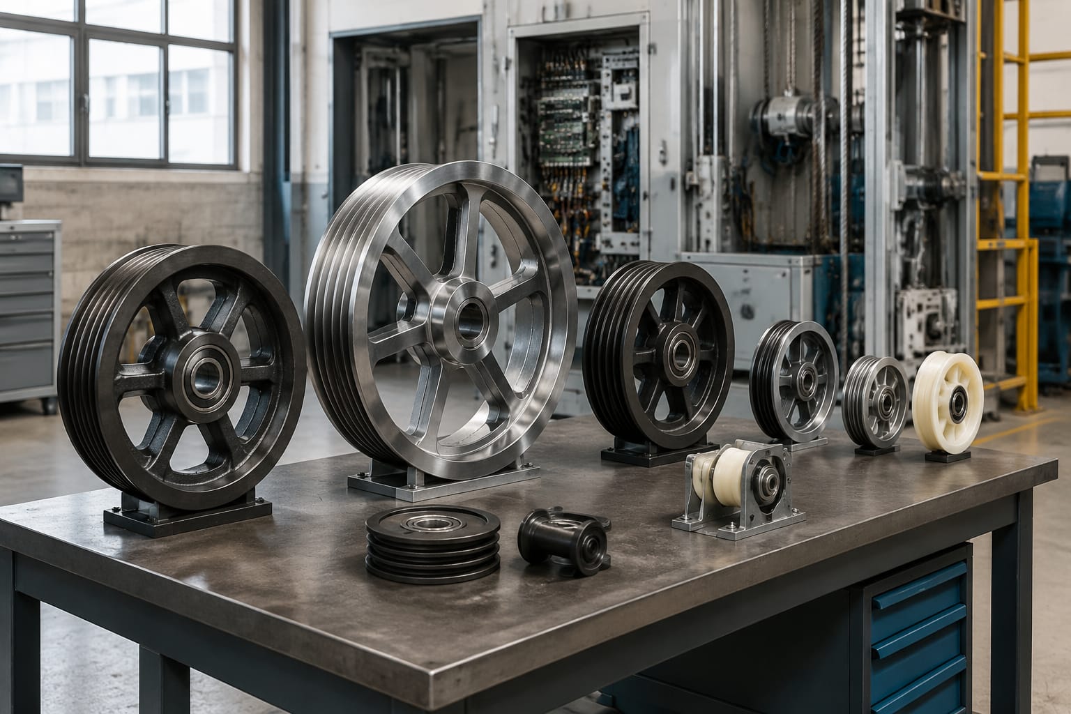
Elevator sheaves are grooved rotating wheels that guide suspension ropes, governor ropes or door-system cables through their intended path. The correct sheave maintains rope alignment, traction and smooth running; the wrong groove profile, bearing arrangement or mounting dimension can accelerate rope wear, create noise and affect lift performance.
For a replacement, do not source by outside diameter alone. Confirm the sheave’s function, rope or cable diameter, groove profile, pitch circle, bore, bearing designation, hub dimensions, keyway or shaft fixing, and the direction of any offset. This information helps distinguish parts that look similar but are not interchangeable.
Traction and deflector sheaves
A traction sheave is the main drive sheave in a traction elevator. It transfers the rotational force of the machine to the suspension ropes through friction between the rope and the grooves. Its condition has a direct effect on levelling, ride quality, rope life and the ability of the car and counterweight system to move as designed.
The traction sheave must be matched precisely to the lift’s original design. Important factors include:
- Number of rope grooves
- Nominal rope diameter
- Groove profile and undercut
- Groove pitch and pitch circle diameter
- Overall diameter and rim width
- Hub length, bore size and keyway
- Machine shaft and fixing arrangement
- Original manufacturer or machine model details
For example, a sheave intended for 8 mm ropes may have the same outside diameter as one for 10 mm ropes, but its groove dimensions and contact pattern will differ. Fitting it can lead to inadequate traction, rope damage or uneven load sharing.
A deflector sheave, often also called a diverting sheave, changes the direction of suspension ropes between the traction machine, car and counterweight. Unlike a traction sheave, it is not intended to transmit driving force. Its role is to preserve the planned rope path and wrap angle while allowing the ropes to run freely.
The terminology is not fully uniform across catalogues. Some suppliers use deflector sheave for a rope-direction wheel near the machine and diverting sheave for one elsewhere in the suspension arrangement. The drawing, location and function should take priority over the name.
| Feature | Traction sheave | Deflector/diverting sheave |
|---|---|---|
| Main purpose | Drives the suspension ropes | Changes rope direction |
| Torque transmission | Yes, through rope-to-groove traction | No, normally free-running |
| Groove requirement | Critical to traction and rope grip | Critical to rope support and alignment |
| Typical mounting | Fitted to machine drive shaft | Mounted on a stationary shaft or axle |
| Key sourcing concern | Machine and rope-system compatibility | Rope path, bearing, shaft and mounting compatibility |
A worn traction sheave should be assessed together with the ropes. Replacing only the sheave where ropes have already become damaged, polished, flattened or unevenly tensioned may not solve the underlying issue. Conversely, new ropes installed on severely worn grooves can bed incorrectly and lose their expected service life.
Where a replacement is required for a particular equipment family, compare the technical drawing and dimensions before choosing a listed part such as a [traction wheel for Otis elevator applications](/products/traction-wheel-switch-otis-elevator-parts-lift-accessories/). A product title alone is not sufficient evidence of fitment.
Diverting, secondary and door sheaves
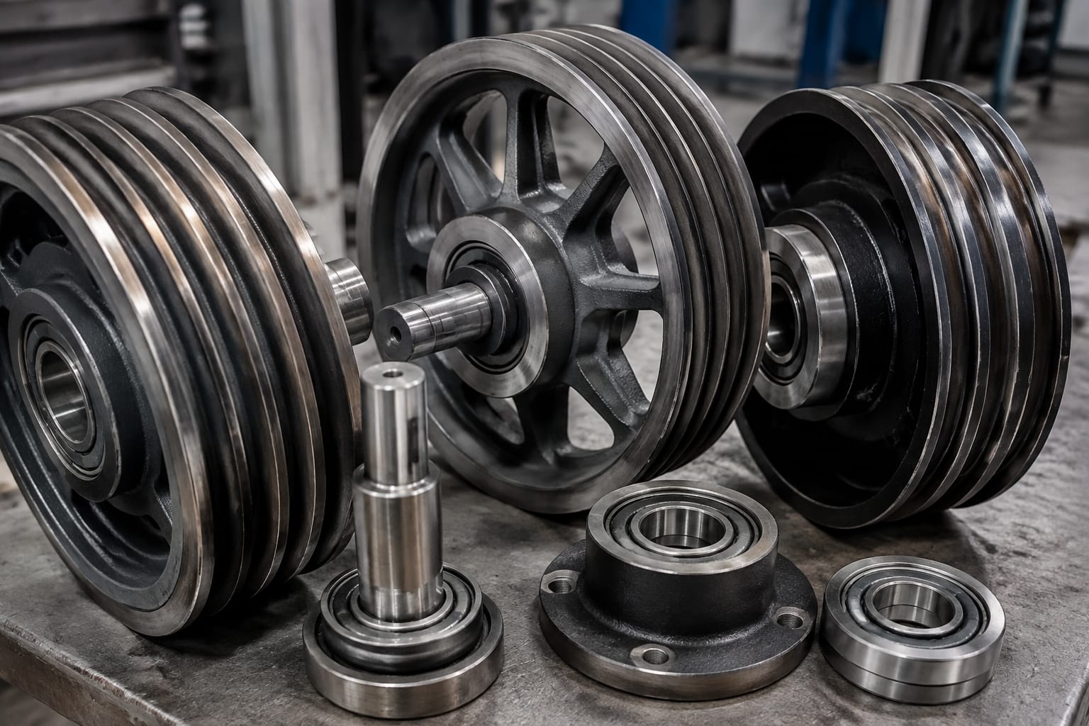
Secondary sheaves are additional rope-supporting sheaves used within the suspension arrangement. Their purpose depends on the lift layout. They may redirect ropes, provide the reeving arrangement needed for the required travel ratio, or maintain clear rope separation around the machine room or overhead equipment.
For all rope-running secondary sheaves, check:
- Rope diameter and groove count
- Groove pitch and rope-centre spacing
- Sheave diameter and allowable rope bending arrangement
- Bearing type, quantity and seating method
- Shaft diameter and retaining method
- Bracket, frame or base mounting dimensions
- Offset from the machine or suspension centre line
A sheave can have correct rope grooves but still be unsuitable because its hub offset moves the ropes out of alignment. This is a common risk when a replacement is selected from a photograph or by rim diameter only.
Door sheaves and change wheels
Door-system sheaves guide the cable, belt or wire rope used to operate landing and car doors. They are generally much smaller than suspension-rope sheaves and are not interchangeable with traction or deflector sheaves. In product catalogues, these components may be called door change wheels, door hanging wheels, pulley wheels, rollers or sheaves depending on their design and role.
A door change wheel commonly redirects a cable in the operator mechanism. A hanging wheel or hanger roller supports and guides the door panel along its track. Although both may have bearings and grooves, their working loads, mounting arrangements and profiles are different.
When identifying door hardware, establish whether the part:
- Supports the door panel on a track.
- Redirects an operating cable.
- Guides a belt or linkage.
- Acts as an eccentric adjustment roller.
- Is part of the car door, landing door or door operator.
Then verify the wheel diameter, face or groove width, bore, bearing number, hub arrangement and fixing details. A [74 x 19 door change wheel with 6203 bearing](/products/74x19x6203-lift-door-change-wheel-elevator-parts/) may be relevant only where those dimensions and the bearing arrangement match the existing door mechanism. Likewise, a [double-groove 140 x 20 door hanging wheel with 6204 bearing](/products/door-hanging-wheel-double-groove-140x20x6204-lift-parts-elevator-accessories/) must be checked against the original hanger geometry and track arrangement.
Do not replace a door pulley with a visually similar wheel without confirming its groove configuration. A single-groove and double-groove wheel can have the same diameter but serve entirely different cable-routing arrangements.
Sheave materials and groove profiles
Elevator sheaves are commonly manufactured from cast iron, steel or engineered materials suited to the application. Material selection depends on duty, loading, manufacturing design, groove treatment and the relevant equipment requirements.
Cast iron is widely used for traction and larger rope sheaves because it can be machined accurately and provides suitable properties for many conventional lift applications. Steel designs may be used where the original system calls for them. Door-system wheels may use metal, nylon or other engineering polymers, depending on whether they run on a track, guide a cable or work within a door operator.
Material cannot be selected independently of the application. A substitute material may have a different friction characteristic, wear pattern, noise level or load response. For a traction application especially, use the material and groove treatment specified or accepted for that machine and rope system.
Common groove forms
The groove is the working surface of a rope sheave. Its form determines how the rope sits, how load is distributed and, for traction sheaves, how much grip is developed.
Common groove forms include:
- U-grooves: Rounded profiles that support the rope with relatively broad contact.
- Undercut U-grooves: Include an undercut intended to increase traction in suitable applications.
- V-grooves: Provide more wedging action but require application-specific assessment due to rope-pressure effects.
- Round or radiused cable grooves: Often used in smaller door and governor-related pulley arrangements.
- Flat or track-running profiles: Used for certain door rollers rather than rope sheaves.
The correct profile is determined by the original lift design. A deeper groove does not automatically mean a better replacement. Excessive groove wear can allow a rope to sit too low, alter the effective running diameter and reduce the intended contact relationship. On a traction sheave, this can contribute to differential rope loading and slipping.
For multiple ropes, compare every groove. Uneven groove wear can cause some ropes to carry more load than others. Measuring only the worst-looking groove is not enough.
Bearings, shafts and mounting
The sheave wheel is only one part of the assembly. Bearing condition, shaft fitment and mounting accuracy determine whether it can rotate smoothly and remain aligned under load.
A traction sheave mounted directly on a machine shaft may use a bore, keyway, taper, hub or other manufacturer-specific connection. It must never be assumed that a matching bore diameter alone establishes compatibility. Confirm the shaft form, key dimensions, locking method, hub length and any retaining components.
Deflector and secondary sheaves usually rotate on a fixed shaft. Their bearing arrangement may include sealed deep-groove ball bearings, rollers, bushes or a proprietary assembly. Check the following:
- Bearing reference and internal clearance where specified
- Number of bearings in the wheel
- Bearing bore, outside diameter and width
- Spacer sleeves, circlips, seals and dust covers
- Shaft diameter and surface condition
- Axial end float and retaining arrangement
- Bracket holes, mounting centres and orientation
A noisy bearing may not be the only fault. A scored shaft, loose bearing seat or distorted mounting bracket can quickly damage a new bearing. Inspect these related parts before fitting a replacement sheave assembly.
For door systems, bearing designation is particularly useful in identification, but it must still be paired with the wheel dimensions and hub layout. Two wheels using a 6203 bearing can differ substantially in width, groove profile and installation method.
Common wear and noise symptoms
Visible wear and operating symptoms can help identify an elevator sheave problem, but they do not by themselves prove which component must be replaced. Isolate the source through inspection and controlled testing by competent lift personnel.
Common symptoms include:
| Symptom | Possible sheave-related causes | Checks required |
|---|---|---|
| Squeal or chirping during travel | Contaminated grooves, rope movement, poor alignment, unsuitable lubrication practices | Inspect ropes, grooves, alignment and applicable maintenance instructions |
| Rumbling or growling | Worn or damaged bearings, rough shaft surface, bearing-seat damage | Rotate unloaded where possible and inspect bearing/shaft condition |
| Repeated rope dust near grooves | Rope abrasion, groove wear, contamination or misalignment | Check rope condition, groove profile and rope path |
| Uneven rope seating | Worn grooves, incorrect rope size, tension imbalance | Measure grooves and assess rope tension using approved methods |
| Car levelling or traction concerns | Worn traction grooves, rope condition, brake or drive issues | Assess the whole drive and suspension system |
| Door noise or hesitation | Worn door pulley, hanger wheel, bearing, track or cable issue | Identify whether the noise follows panel movement or cable travel |
| Visible side wear on ropes | Misaligned sheave, displaced bracket, incorrect spacing | Check rope-centre lines and mounting position |
Avoid applying grease or oil to traction ropes or traction sheave grooves unless the relevant lift manufacturer’s instructions explicitly require it. Unapproved lubrication can change traction and attract abrasive contamination.
Cracks, broken rims, loose hubs, seized bearings, severe groove damage or rope derailment are conditions requiring the lift to be handled according to the site’s safety procedure and by appropriately competent personnel. Do not treat a visibly damaged sheave as a routine noise complaint.
Inspection and measurement checklist
Before measuring, make the equipment safe, isolate it in accordance with site procedures and ensure access is controlled. Measurement should be carried out by trained personnel using calibrated or suitable tools.
Record measurements in millimetres unless the original drawing uses another unit. Include photographs with a scale reference, but use photographs as supporting evidence rather than the sole source of dimensions.
What to inspect
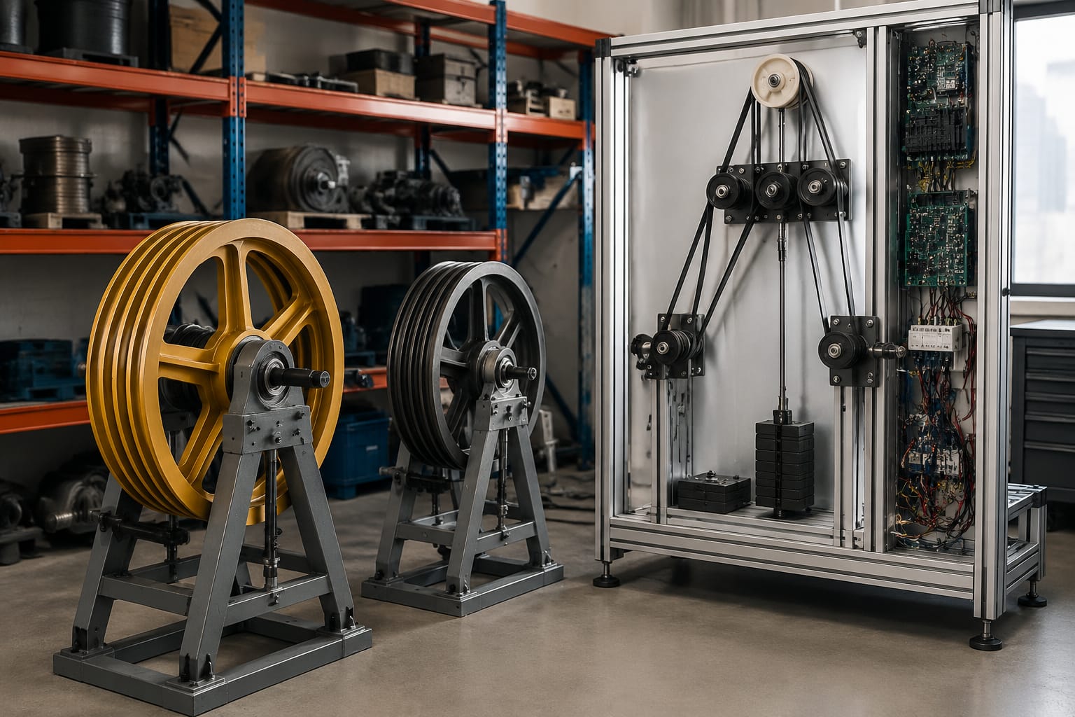
- Confirm the sheave’s location and function in the system.
- Count ropes, cables or grooves and note unused grooves.
- Look for polished groove bottoms, sharp edges, pitting, cracking and corrosion.
- Check whether all ropes sit to a similar depth.
- Inspect for rope dust, metal particles, debris or lubricant contamination.
- Rotate the sheave where safely possible and feel for roughness, tight spots or excessive play.
- Check shaft, bracket and fasteners for movement, damage or corrosion.
- Examine rope alignment as ropes enter and leave the sheave.
- Compare the condition of adjacent sheaves, as one alignment issue may affect several components.
Dimensions to measure
For a rope sheave, record:
- Outside diameter of the rim.
- Pitch circle diameter where available from a drawing or accurate measurement process.
- Face width.
- Number of grooves.
- Groove pitch, measured centre to centre.
- Groove radius, width, depth and profile form.
- Nominal rope diameter.
- Bore diameter.
- Keyway width and depth, if present.
- Hub diameter, hub length and hub offset.
- Overall width.
- Bearing number, bore and seating arrangement.
- Shaft diameter and usable shaft length.
- Mounting-hole size, centres and bracket dimensions.
For a door sheave or roller, include the wheel diameter, wheel width, groove dimensions, bearing marking, bore, hub projection and the exact position of washers, spacers and retaining clips. The stack-up order is often essential to retaining correct door alignment after replacement.
A vernier caliper is useful for bores, widths and bearing-related dimensions. A groove gauge or profile template can support groove assessment. Measurements taken from a worn groove must be identified as worn dimensions, not treated as the original specification.
Information needed for sourcing
A useful sourcing enquiry gives the supplier enough information to check fitment without guessing. The minimum information varies by component, but the following package is practical for most elevator sheave replacements:
- Lift brand, controller or machine details where relevant
- Existing part number and any markings on the wheel, bearing or assembly
- Component function and installation location
- Clear photographs of front, rear, side, bore, mounting and groove profile
- Dimensioned sketch with all critical measurements
- Number of ropes or cables and their nominal diameter
- Groove count, pitch and profile
- Bearing number and shaft/bore details
- Material requirement where known
- Quantity required
- Whether the request is for a bare wheel, wheel with bearings, complete shaft assembly or mounted bracket assembly
For B2B purchasing, also define the unit of supply. A “sheave” may mean a bare machined wheel to one buyer and a complete wheel, bearing and shaft assembly to another. Clarifying this prevents mismatched quotations and incomplete deliveries.
When the original part number is unavailable, do not rely on a brand name and rough diameter. Supply the measurement record and photographs. Kelevator supports B2B importers, distributors, maintenance contractors, modernisation companies and OEM buyers with multi-brand elevator spare-parts sourcing; detailed technical identification remains important for checking a proposed replacement.
Common sourcing mistakes
The following shortcuts regularly create compatibility problems:
- Ordering by outside diameter only.
- Omitting rope diameter or groove profile.
- Treating deflector and traction sheaves as equivalent.
- Ignoring hub offset and overall assembly width.
- Ordering a wheel without checking whether bearings are included.
- Reusing damaged bearings, shafts or spacers with a new wheel.
- Replacing one component in a multi-rope system without evaluating rope condition and groove wear.
- Choosing a door roller by bearing number without confirming track, groove and hub geometry.
Alignment and testing after replacement
Replacement work should be performed by competent lift technicians following the equipment manufacturer’s instructions, site safety requirements and the applicable maintenance process. A correctly specified sheave can still fail prematurely when installed out of alignment or with incorrect rope tension.
After installation, verify that the sheave is seated correctly, secured with the required hardware and free from contact with guards, brackets or adjacent components. Confirm that bearings are retained properly and that any covers or guards are restored.
Then check:
- Rope or cable entry and exit alignment.
- Correct seating of every rope in its groove.
- Uniform rope tension, using the approved method for the installation.
- Smooth rotation without binding, lateral movement or abnormal bearing noise.
- Correct clearance to fixed components through the complete travel path.
- Door travel, closing action and reversal behaviour for door-system components.
- Normal lift operation, ride quality and levelling under the prescribed test procedure.
- Any manufacturer-required checks following work on traction or suspension components.
For traction sheaves, monitor early operation for unusual rope dust, slip indications, noise or changes in rope seating. For door sheaves and hanging wheels, confirm the panel remains level, clears the sill and jamb correctly, and travels without rubbing or cable misrouting.
The practical next step is to prepare a dimensioned identification sheet before requesting quotations. A complete record of the existing sheave, rope or cable details, bearing arrangement and mounting geometry provides the basis for a technically meaningful replacement comparison.