
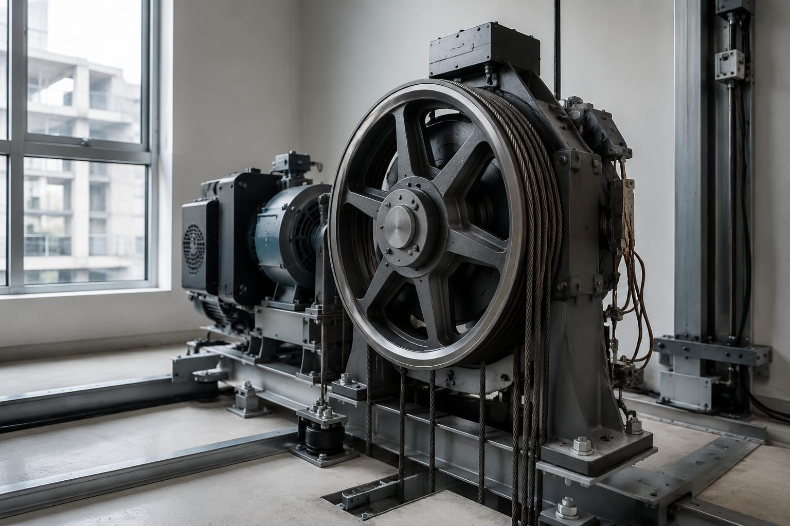
An elevator traction sheave transfers motor torque to the suspension members that move the car and counterweight. Its condition is critical: worn, polished or uneven grooves can reduce traction, accelerate rope or belt damage, create vibration, and cause poor levelling or slip-related faults.
When sourcing a replacement elevator traction sheave, do not select it by outside diameter alone. Confirm the suspension medium, groove geometry, pitch circle diameter, number and spacing of grooves, bore and shaft connection, machine model, and the original part identification where available. A physically similar sheave may still be unsafe or unsuitable for the machine and suspension system.
How a traction sheave works
The traction sheave is the driven wheel on a traction lift machine. As the motor turns the sheave, friction between the groove surface and the steel wire ropes or coated steel belts creates enough grip to move the elevator car and counterweight in opposite directions.
The system relies on a controlled balance between several factors:
- Sheave diameter and rotational speed
- Suspension-member type, diameter or width, and construction
- Groove profile and surface condition
- Wrap angle around the sheave
- Car, counterweight and load balance
- Rope or belt tension equalisation
- Contamination from oil, water, dust or cleaning products
The sheave should provide consistent traction without crushing, cutting or excessively bending the ropes or belts. This is why groove condition matters as much as the wheel itself. A sheave with grooves that are too worn or too deep may change the way load is shared between suspension members. A groove that is too aggressive may create high local stress and shorten rope or belt life.
In a geared machine, the traction sheave is usually mounted on the output shaft. In many gearless machines, it is integrated with or directly fitted to the motor rotor. The mounting arrangement, shaft interface and encoder-related machine configuration must be identified before ordering any replacement.
Steel-rope and steel-belt applications
Steel wire ropes and coated steel belts do not use the same traction interface. Replacement selection must start with the suspension type fitted to the lift.
Steel wire-rope traction sheaves
Conventional traction lifts generally use multiple round steel wire ropes. Their sheaves have one groove per rope, with the number of grooves matching the suspension arrangement. Common groove forms include U-grooves, undercut U-grooves and V-type grooves, but the correct form depends on the original machine and rope specification.
A rope sheave must match:
- Rope nominal diameter
- Number of ropes
- Groove count and centre-to-centre pitch
- Groove profile, depth and undercut
- Traction sheave pitch diameter
- Rope lay and construction where relevant to the machine design
Do not assume that a groove suitable for a nominally similar rope diameter will perform correctly. Small profile differences can alter traction and contact pressure.
Steel-belt traction sheaves
Steel-belt systems use flat, coated belts with embedded steel cords rather than round ropes. Their traction sheaves have a specifically designed belt track or groove pattern. Belt width, cord configuration, coating, groove form and pulley diameter are all system-specific.
A steel-belt sheave must be selected for the exact belt family and machine application. Mixing components across belt generations or manufacturer systems can lead to poor seating, coating damage, inconsistent traction and premature belt failure.
For example, a [3300 steel-belt traction sheave](/products/id-steel-belt-traction-sheave-3300-elevator-parts/) should be cross-checked against the installed machine and belt arrangement rather than treated as a general-purpose flat-belt pulley. Likewise, product descriptions such as [traction steel-belt elevator parts](/products/traction-steel-belt-otis-elevator-parts-lift-parts/) are useful starting points for identification, but the final selection still depends on matching the original assembly details.
Why rope and belt sheaves are not interchangeable
Round ropes contact the groove along a curved surface; belts rely on a different contact pattern across their width. The required groove geometry, pressure distribution and bending behaviour are therefore different. A steel-rope traction sheave cannot be adapted for a steel-belt installation, and a belt sheave should never be used with wire ropes.
Groove profiles and traction conditions
Groove profile controls how the suspension member sits in the sheave and how much friction is available to drive the lift. The aim is stable traction with even load distribution, not maximum friction at any cost.
For rope applications, common profiles have different purposes:
| Groove profile | Typical traction behaviour | Main consideration |
|---|---|---|
| Round or U-groove | Moderate grip with broad rope support | Can lose traction as the groove becomes polished or enlarged |
| Undercut U-groove | Higher grip than a plain U-groove | Requires correct rope type and careful wear monitoring |
| V-type groove | Strong wedging action and higher traction | Can increase rope pressure and wear if not specified for the system |
| Special manufacturer profile | Designed for a particular machine and suspension system | Must be duplicated accurately; do not substitute by appearance |
The correct groove profile is set by the lift design. It should not be changed casually to solve a traction complaint. Increasing groove grip may seem useful where slip occurs, but it can create uneven tension, higher rope wear, noise or a different failure mode.
Traction conditions also depend on the condition of the rope or belt. Oil contamination can reduce grip, while a rough or corroded sheave may damage the suspension member. Unequal rope tension means individual ropes carry different loads and wear grooves at different rates. On belt systems, damaged coating, debris in the tracks or misalignment can affect running even where the sheave appears sound.
Avoid dressing, machining or re-grooving a traction sheave unless the lift manufacturer’s requirements, available material allowance and dimensional limits are known. Machining changes groove geometry and may alter the pitch diameter. A sheave that appears recoverable can become incompatible after material removal.
Signs of sheave and belt wear
Routine inspection should identify groove wear before it results in suspension-member damage or unreliable operation. The most useful comparison is across all grooves or tracks, not just one visible area.
Signs on steel-rope traction sheaves
Look for:
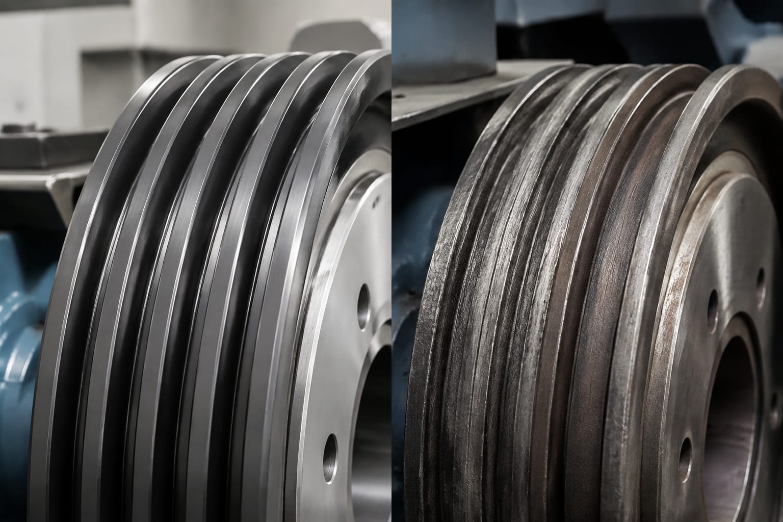
- Grooves with a polished, mirror-like surface that may indicate reduced traction
- Uneven groove depth or width from rope-to-rope
- Sharp groove shoulders, scoring, pitting or corrosion
- Rope contact marks sitting unusually low, high or off-centre in the groove
- Metal particles or abnormal black residue around the sheave
- Rope vibration, audible squeal, slip or inconsistent ride behaviour
- Unequal rope tensions and visibly uneven rope wear
A rope running lower in one groove than in adjacent grooves can signal a worn groove, a rope diameter issue, unequal tension or an incorrect replacement rope. Determine the cause before replacing only the sheave.
Signs on steel belts and belt sheaves
Inspect for:
- Cracks, cuts, exposed cords or damaged belt coating
- Uneven belt tracking across the sheave
- Polished, damaged or contaminated belt tracks
- Build-up of coating debris in grooves or around guards
- Belt edges rubbing against guides, covers or adjacent components
- Noise, vibration, tracking faults or evidence of belt movement across the track
Belt defects demand particular care because the external coating condition can indicate deeper damage. Do not judge continued serviceability only by whether the lift is still running. Follow the applicable equipment manufacturer’s inspection and replacement criteria.
Do not diagnose from one symptom alone
Slip, noise, rough travel and levelling complaints may originate elsewhere: brake performance, motor control, encoder faults, rope tension, bearing wear, contamination, imbalance or compensation-system issues can produce similar symptoms. The traction sheave should be inspected as part of a complete machine and suspension assessment.
Measure diameter, grooves and shaft interface
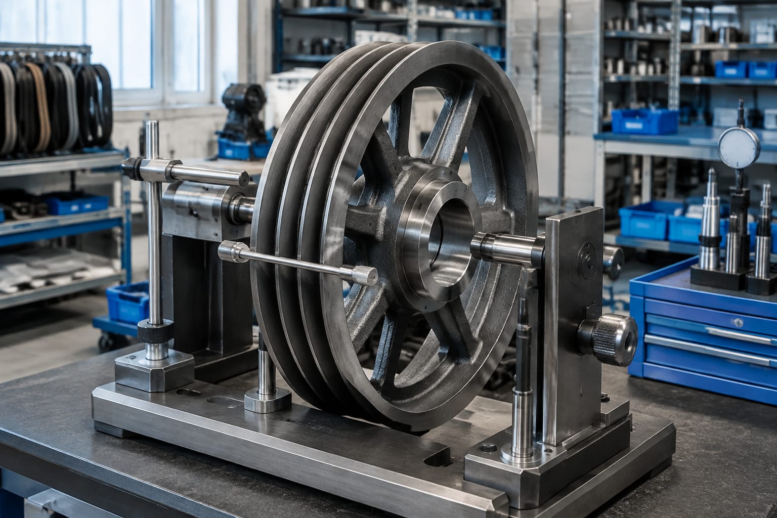
Accurate measurement prevents the most common sourcing error: ordering a wheel that looks correct but does not fit or does not preserve the original traction geometry. Record measurements from the existing part only after confirming whether wear may have altered them. Original drawings, machine documentation and part numbers are more reliable references when available.
Use calibrated measuring tools and record the method used. Photographs with a scale can support identification but should not be the sole basis for manufacture or supply.
Essential sheave dimensions
| Measurement | Why it matters | What to record |
|---|---|---|
| Outside diameter | Helps identify the part and physical clearance | Diameter at an unworn reference area where possible |
| Pitch diameter | Directly affects rope or belt travel and machine design | Manufacturer value or verified groove reference |
| Groove or track count | Must match the suspension arrangement | Total number, including unused positions if originally present |
| Groove pitch | Controls rope or belt alignment | Centre-to-centre distance between adjacent grooves or tracks |
| Groove profile | Determines seating and traction | Width, radius, depth, undercut or track shape |
| Face width | Must accommodate every groove or belt track | Overall working width and edge margins |
| Bore diameter | Determines shaft fit | Bore size and any tolerance information |
| Keyway, spline or taper | Defines torque transmission and orientation | Width, depth, length, taper details and position |
| Hub dimensions | Affects mounting and clearance | Hub diameter, length, offset and retaining arrangement |
| Bolt pattern, if fitted | Needed for bolted designs | Hole count, PCD, thread or clearance-hole size |
For steel rope systems, measure the actual groove profile using suitable gauges or obtain the original profile drawing. Measuring only the top opening of a groove is insufficient; the contact radius and undercut determine how the rope is supported.
For steel belts, record belt width, number of belts, belt-to-belt spacing, track form and guidance arrangement. Confirm the specific belt designation from machine records or markings where permitted.
Shaft and mounting details are critical
The bore is not simply a hole through the sheave. The shaft interface may use a parallel key, taper lock, tapered bore, spline, shrink fit, clamping arrangement or an integrated rotor assembly. The sheave’s axial position can also be essential to rope or belt alignment.
Before releasing a purchase order, verify:
- Shaft diameter and fit type.
- Keyway or spline dimensions and orientation.
- Hub offset and mounting face location.
- Retaining nut, bolt, locking plate or clamp arrangement.
- Required balance condition or assembly requirement.
- Clearance to guards, bearings, encoder parts and machine frame.
Never force a bore, keyway or hub to fit in the field. Unauthorised modification can weaken the component, create runout or change the alignment of the suspension members.
Check machine and suspension compatibility
A complete compatibility check links the replacement elevator traction sheave to the actual lift machine, not merely to the building’s lift brand.
Start with the machine nameplate and available documentation. Capture the machine manufacturer, model, serial number, original sheave part number, lifting capacity, rated speed, suspension ratio, rope or belt specification, and number of suspension members. A clear photo of the full machine arrangement, subject to site access rules, can help a sourcing team identify features that a part number alone does not show.
Check these areas together:
- Machine compatibility: machine model, drive configuration, shaft design, mounting position and rotation direction where relevant.
- Suspension compatibility: rope diameter or belt type, count, spacing, construction and manufacturer-approved replacement requirements.
- Dimensional compatibility: pitch diameter, groove or track profile, face width, hub position and shaft interface.
- System compatibility: car and counterweight balance, wrap angle, diverting pulley arrangement, compensation equipment and tension equalisation.
- Control and safety impact: work required to safely remove and refit the sheave, re-tension suspension members, inspect guards and verify operation afterwards.
A component may be described commercially as a traction pulley. Confirm whether it is the main traction sheave, a diverter sheave, deflector pulley or governor-related pulley, as these components have different duties and interfaces. For a rope application, a [5500 traction steel pulley](/products/id-traction-steel-pulley-5500-elevator-parts/) should be compared with the installed part’s role, dimensions and machine fitment before selection.
Replacement planning and handling
Sheave replacement is a machine-room or shaft-top mechanical task that requires competent lift personnel, an approved isolation process and proper lifting arrangements. The component can be heavy, and work around suspension members, rotating machinery and the car-counterweight system carries significant risk.
Plan the work before the lift is taken out of service.
Replacement planning checklist
- Confirm the fault or wear finding and document baseline measurements.
- Verify the exact replacement specification against machine and suspension information.
- Review whether ropes or belts, bearings, retainers, guards or tensioning components also require attention.
- Establish the lifting method, lifting points and weight information from reliable documentation.
- Isolate electrical power and secure the car and counterweight in accordance with the site procedure and equipment requirements.
- Arrange clean storage for the new component so grooves and machined faces are protected.
- Keep oil, grease, paint and abrasive material away from rope or belt contact surfaces unless the manufacturer specifically requires otherwise.
- Plan re-tensioning, alignment checks and post-installation testing before the work begins.
Do not roll a sheave over rough surfaces or allow it to strike another component. Impact can damage groove edges, bearing seats, keyways or the machined bore. Store it flat or in the orientation recommended for the part, on protected supports that do not mark the traction surface.
Replacing the sheave alone may not correct a system with severely worn ropes, damaged belts or unequal tension. Evaluate the suspension members as a set. Mixing new and worn ropes or belts, or leaving a severely worn suspension component on a new sheave, can lead to rapid uneven wear.
Inspection after installation
Post-installation inspection confirms that the sheave is correctly fitted and that the suspension system is running as intended. It is not enough for the lift to make one successful trip.
Before returning the lift to normal service, verify:
- The sheave is fully seated and secured using the correct retaining arrangement.
- Guards and covers are restored without contact or interference.
- Ropes or belts sit correctly in every groove or track.
- The suspension members run centrally without edge rubbing or crossover.
- Alignment with diverting sheaves and other pulleys is correct.
- Rope tensions are equalised using the applicable method and equipment requirements.
- There is no unusual runout, vibration, rubbing, noise or debris generation.
- Travel, acceleration, deceleration, levelling and stopping behaviour are satisfactory.
- The machine area is clean, with no loose tools, fasteners or contamination near moving parts.
Reinspect after initial running and during the next planned maintenance visit. Early follow-up is useful because a tension or tracking issue may only become apparent after the suspension members have settled.
Record the part fitted, measurements, condition of removed components, tensioning work, observations and any remaining recommendations in the maintenance documentation. This provides a useful baseline for later wear checks and future sourcing.
FAQ
Can a worn elevator traction sheave be re-grooved?
Sometimes, but only where the equipment manufacturer permits it and the finished groove profile, pitch diameter, material condition and safety requirements can be confirmed. Re-grooving without these controls can alter traction and suspension-member life. Replacement is often the more predictable option when wear limits or dimensional history are uncertain.
How do I know whether the sheave or the ropes are causing slip?
Inspect both. Rope condition, lubrication or contamination, tension balance, groove polish and groove geometry all influence traction. Electrical and brake faults can also resemble traction problems. A systematic machine and suspension inspection is needed before assigning the cause.
Is the outside diameter enough to order a replacement sheave?
No. Outside diameter is only one identification point. The groove profile, pitch diameter, groove count and pitch, bore, keyway or spline, hub offset, machine model and suspension type must also match.
Should ropes or belts be changed with the traction sheave?
The decision depends on their condition, wear limits, compatibility and the cause of sheave wear. If the suspension members are damaged, contaminated, unevenly worn or incompatible with the new sheave, replacing only the sheave may not provide a reliable result. Follow the equipment manufacturer’s requirements for the installed system.
For sourcing, prepare the machine identification, original part number, full dimensional record and clear photographs of the sheave and suspension arrangement. Kelevator supplies multi-brand elevator spare parts for B2B buyers; these details help a distributor, maintenance contractor or sourcing team verify the correct traction-sheave configuration before proceeding.