
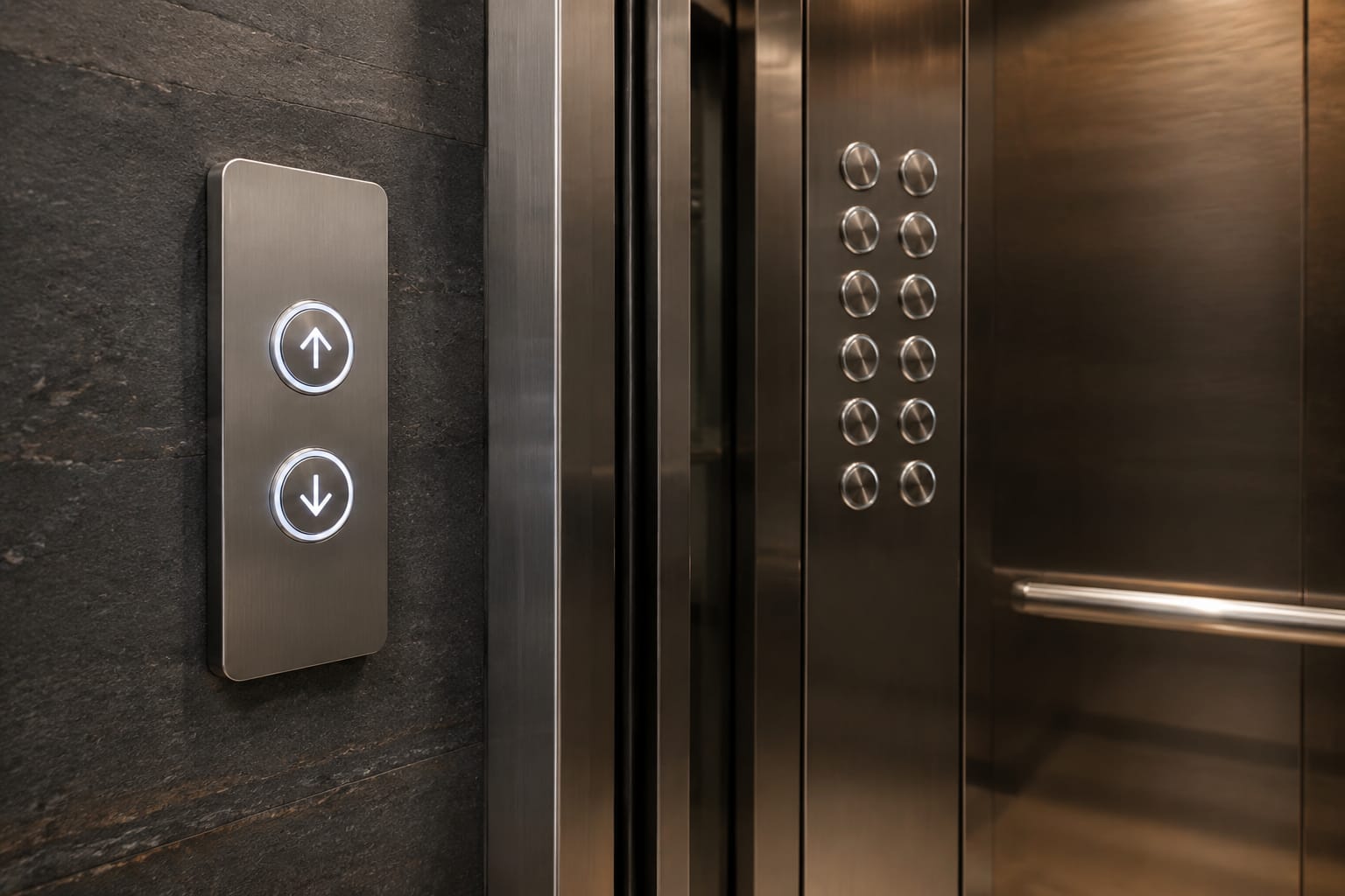
Replacing KONE elevator buttons correctly means matching more than the visible cap. The correct part must suit the panel position, mounting cut-out, illumination method, connector arrangement and, where applicable, the call-board or car operating panel board it connects to. A button that looks similar may not fit securely, light correctly or communicate with the existing electronics.
For lift maintenance teams and sourcing professionals in India, start by recording the panel details before removing any part. Clear photographs, accurate measurements and all printed codes reduce the risk of ordering a visually similar but electrically unsuitable replacement.
KONE car buttons versus landing buttons
KONE elevator buttons generally fall into two different functional groups: car operating panel buttons inside the lift car, and landing call buttons outside the lift at each floor. They may share a visual style, but they are not automatically interchangeable.
Car buttons are installed on the car operating panel (COP). They can include floor-selection buttons, door open and door close buttons, alarm buttons, emergency communication buttons, fan or light controls, and service functions. Their labels, legends and wiring logic are tied to the car panel and lift controller configuration.
Landing buttons are fitted to a landing operating panel (LOP), hall station or call panel. Depending on the floor and installation, they may have:
- One call direction, typically up at the lowest served floor or down at the highest served floor
- Up and down call buttons at intermediate floors
- A key switch, fire service function or access-control provision
- A position indicator, direction arrows or display integrated with the call assembly
The first check is therefore simple: identify whether the failed KONE elevator button is in the car or on the landing. Then identify its function. A car button marked “5” cannot be substituted with a landing up-call button even when the front diameter appears identical.
| Check point | Car operating panel button | Landing call button |
|---|---|---|
| Usual location | Inside the lift car | Outside the lift at a floor |
| Main purpose | Select floor or car function | Register an up/down hall call |
| Typical labels | Floor numbers, door symbols, alarm | Up arrow, down arrow, access symbol |
| Associated electronics | COP wiring and car/controller interface | Landing call board, display or hall network |
| Key replacement risk | Wrong legend or car-panel communication | Wrong direction, board version or network connection |
Some assemblies combine buttons and electronic boards in one unit. In such cases, assess the complete assembly rather than treating the button as an isolated spare.
Identify the panel and elevator model
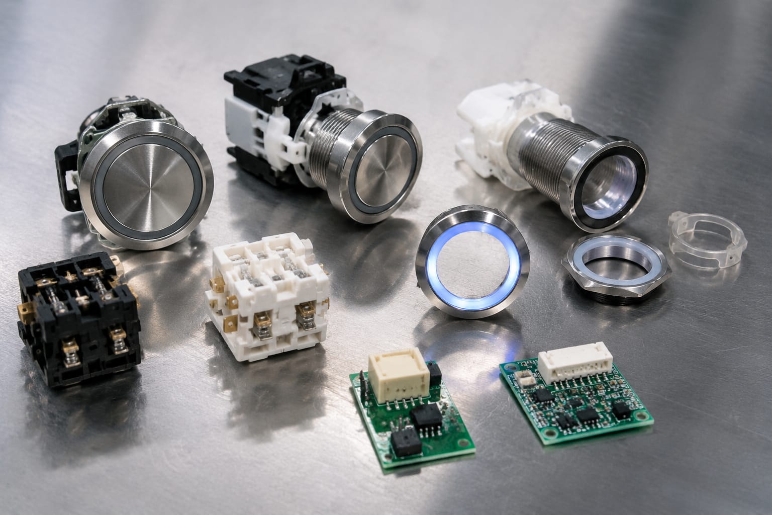
Panel identification is more useful than relying only on the lift brand. KONE installations can have different panel generations, finishes, button families and electronics depending on the building age, modernisation history and project specification.
Before sourcing a replacement, record:
- Whether it is a COP, LOP, destination operating panel or integrated display/call unit.
- The exact location: car, main landing, intermediate floor, rear entrance panel or service panel.
- The button function and visible symbol or floor marking.
- Any model, product, board or panel reference printed on labels, the rear of the panel or the electronic board.
- The lift’s controller or system details where accessible to an authorised technician.
- Whether the panel was changed during an earlier modernisation.
Do not assume that all lifts in the same building use the same parts. A building may have more than one lift group, a goods lift with different fixtures, or cars refurbished at different times. Compare the removed part with the intended location in the actual lift.
A complete photograph of the panel helps establish the fixture family and layout. Close-up images of the front, rear, terminals, connector and any label are more useful than a single front-facing image. Where a display or call interface is involved, photographs of the board markings and cable positions matter as much as the visible fascia.
For related electronic assemblies, compare the relevant KONE car button board parts against the existing board reference rather than selecting by appearance alone.
Treat logos and styling as clues, not proof
A KONE logo, a matching metal finish or a familiar-looking symbol is not enough to establish compatibility. Panels may have been renewed, buttons may have been replaced individually before, and similar products can use different rear housings or pin arrangements.
Use the original part number, board code and physical evidence together. If a full code is partially obscured, send a high-resolution photograph rather than guessing the missing characters.
Match button dimensions and mounting
Physical fit is the next critical check. KONE elevator buttons can differ in face shape, bezel size, body depth, retaining method and panel cut-out even when their front faces look alike.
Measure the removed button using a vernier calliper where possible. Record dimensions in millimetres and do not round them unnecessarily.
Important measurements include:
- Front face diameter, width and height
- Visible bezel diameter or outer dimensions
- Panel cut-out diameter or rectangular opening
- Body depth behind the panel
- Clearance needed behind the panel for connectors and wiring
- Distance between fixing points for modules with screws or clips
- Thickness of the mounting panel, where retention depends on it
For round buttons, distinguish between the diameter of the visible front ring and the diameter of the panel cut-out. These are often different. For rectangular buttons, record both width and height and note the orientation.
Check the retention method
A button may use snap clips, a threaded retaining ring, screws, a carrier frame or a larger integrated module. Forcing the wrong mounting method can crack the panel, damage clips or leave the button loose after installation.
Inspect the rear of the original part for:
- Locking tabs and their position
- Threaded collars or retaining nuts
- Screw holes and screw spacing
- Carrier frames or clip-on modules
- Alignment tabs that prevent incorrect rotation
- Separate legend inserts, caps or illumination components
A replacement should sit flush with the panel and remain stable through repeated operation. Do not enlarge a panel cut-out merely to make an available part fit unless the modernisation design and panel integrity have been assessed. Such alterations can compromise the finish, ingress protection and future serviceability.
Check illumination voltage and colour
Illumination is a functional compatibility point, not only an aesthetic choice. Buttons may use LEDs, lamps or integrated light modules, and their required supply voltage, polarity and control arrangement can vary.
Check whether the original button has:
- A continuously lit legend or halo
- A light that activates only after a call is registered
- Separate illumination and acknowledgement circuits
- One colour in standby and another when selected
- An integrated LED or a separately replaceable lamp or LED board
- A polarity marking for DC supply
Record the observed colour in both states: idle and active. For example, a button may have a white legend when idle and an amber or red confirmation light after selection. Do not specify only “illuminated” when sourcing the part.
The voltage should be confirmed from the original part documentation, board marking, wiring diagram or approved test method. Avoid applying an assumed voltage directly to an unknown button. Incorrect voltage can damage LEDs, cause weak illumination or lead to failure of the associated board.
Colour consistency matters in multi-lift sites
In offices, hospitals, hotels and residential towers, inconsistent button illumination can confuse passengers and make a partial repair look incomplete. Match the existing visual behaviour where practical, particularly for direction arrows, alarm buttons and accessibility-related controls.
Colour alone is still not a valid basis for selection. The correct button must first match the mechanical and electrical arrangement. If an older illuminated button is unavailable, assess whether a compatible complete fixture upgrade is more suitable than mixing unmatched parts within one panel.
Compare button and call-board codes
Part codes provide the strongest compatibility evidence when available. Check every number, letter, suffix and revision mark on the button, rear housing, PCB label, display board and cable label.
A code may indicate the button family, display type, connector version, revision or production batch. Two boards with similar descriptions can have different communication interfaces or firmware requirements. A small suffix difference may be significant.
When replacing only a button, compare:
- Button part number or moulded code
- Legend code or symbol version
- Lighting specification
- Connector and terminal arrangement
- Revision marking where shown
When the button is linked to a call board, also compare:
- Board part number and revision
- Number and type of button inputs
- Display and arrow connections
- Power input marking
- Communication or bus connectors
- Mounting-hole pattern and enclosure dimensions
A landing unit with a display may require board-level matching. Review the relevant KONE call display board options using the existing board code and connector layout as the comparison baseline.
Do not interchange boards based on similar displays
A display that has the same screen size or similar numerals can still use a different protocol, power requirement or connector order. This is especially important for LCD call panels. Before replacing one, verify the exact board markings and pin layout against the existing LCD display call-board assembly.
Where a code cannot be read, document the panel layout, board dimensions, connector count and cable labels. This gives a supplier enough information to assess possible matches without falsely treating a visual resemblance as confirmation.
Inspect connectors and wiring
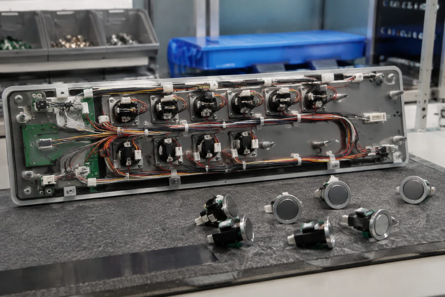
The rear connection is often where an otherwise correct-looking KONE elevator button proves incompatible. Inspect the original connector before unplugging it, and photograph it in place to preserve wire orientation and routing.
Check:
- Connector type: plug, socket, ribbon cable, terminal block or individual terminals
- Pin count and pin spacing
- Keying notch, latch location and connector orientation
- Cable colour codes and printed wire labels
- Numbering on terminals or PCB headers
- Whether the button has separate leads for common, signal and illumination
- Condition of terminals, crimp contacts and insulation
A connector that physically plugs in is not necessarily wired identically. Pin assignments can vary between board revisions. Confirm terminal designations or wiring documentation before energising a replacement.
Look for the actual cause of failure
A non-working button does not always mean the button itself has failed. Before ordering, inspect for:
- Loose or damaged connector pins
- Broken wires at the panel hinge or cable flex point
- Oxidation, moisture marks or contamination
- A failed LED or lamp circuit
- Cracked solder joints on a call board
- Several buttons failing together, which may indicate a board, supply or communication issue
- A button that operates mechanically but is blocked by access control or controller logic
Replacing a sound button will not resolve a faulty board or wiring issue. Conversely, replacing a board without testing the individual button can increase repair cost unnecessarily.
Lift panels and controller circuits should be accessed only by competent personnel following the site’s isolation and safety procedures. Never work on a live lift circuit simply to identify a connector or test a lamp.
Test operation after replacement
After installation, test the replaced part as part of the complete passenger interface, not just as a mechanical pushbutton. Restore covers and ensure the button sits correctly before carrying out functional checks.
For a car button, confirm that it:
- Moves freely and returns correctly after pressing.
- Illuminates as expected in its idle and registered states.
- Registers the intended floor selection.
- Does not trigger an adjacent button or loose panel movement.
- Clears or changes indication appropriately after the lift serves the call.
- Works consistently over repeated presses.
For a landing button, confirm that it:
- Registers the correct up or down direction.
- Illuminates or acknowledges the call as designed.
- Sends the call to the relevant lift group.
- Clears the call when a lift responds, according to the system’s normal operation.
- Does not affect the display, direction arrows or nearby controls.
- Operates consistently after panel reassembly.
Where the panel includes access control, fire service, emergency features or destination control, do not infer correct operation from a basic button press. Test only within the authorised maintenance procedure for that installation. Safety and emergency functions may require additional checks under site rules and the lift manufacturer’s documentation.
Record the old and new part codes, date of replacement and test result in the maintenance log. This makes future fault finding more efficient, especially where multiple identical panels are installed.
Information to send a parts supplier
A complete enquiry helps a supplier distinguish between an exact replacement, a potentially compatible alternative and a part that needs further verification. It also prevents unnecessary back-and-forth when the lift is out of service or a modernisation schedule is underway.
Send the following information:
- Lift brand and known model or controller details
- Whether the item is a COP button, landing call button, display board or complete panel module
- Button function, floor marking, symbol or direction
- Clear front and rear photographs of the removed item
- Photographs of the full panel and the installed position
- All part numbers, PCB codes, revisions and cable labels
- Exact measurements in millimetres, including cut-out and body depth
- Illumination type, voltage marking if known, and idle/active colours
- Connector photographs showing pin count, keying and wire positions
- Quantity required and whether all units must match as a set
- Details of related faults, such as failed display, intermittent response or multiple non-working buttons
For B2B importers, distributors, maintenance contractors and OEM sourcing teams, specify whether the request is for a single repair, recurring stock, a panel refurbishment or a planned modernisation. This context helps determine whether an exact matching spare or a broader replacement solution should be evaluated.
Kelevator supplies multi-brand elevator spare parts for B2B buyers, including maintenance contractors, distributors, importers and OEM sourcing teams. Use the identification details above to request a compatibility review with the original part evidence, rather than ordering solely from a front photograph.
Common replacement mistakes to avoid
The most common error is choosing by appearance alone. Similar button faces may have different cut-outs, body depths, lighting circuits or board interfaces.
Other avoidable mistakes include:
- Ordering a car button for a landing panel, or the reverse
- Omitting the button’s active illumination colour
- Measuring only the front bezel and not the panel cut-out
- Ignoring part-code suffixes or PCB revision marks
- Reusing damaged connectors or loose terminals
- Replacing a button when several failed controls point to a board or power fault
- Altering panel cut-outs without considering retention, finish and future replacements
- Energising an unverified part before checking voltage and pin assignments
A methodical comparison of function, physical dimensions, illumination, codes and wiring is usually faster than repeated trial fitting.
FAQ
Can a generic lift button replace a KONE elevator button?
Only when its mechanical, electrical and interface requirements have been verified against the original. A generic-looking button may fit the panel but have the wrong illumination voltage, terminal layout or mounting method. For networked or board-connected panels, board compatibility must also be confirmed.
Is the code on the front button enough to order a replacement?
Not always. The front may show only a floor number, symbol or cosmetic marking. Check the rear housing, PCB, connector and panel labels for the useful technical code. Photographs of both sides are preferable.
Why does a newly fitted button light up but not register a call?
Possible causes include incorrect signal wiring, incompatible pin assignment, a faulty call board, a controller communication issue or access-control programming. Illumination confirms only part of the circuit; it does not prove the call signal is reaching and being accepted by the lift system.
Should the whole call panel be replaced if one button fails?
Not necessarily. Replace the individual button when it is confirmed as the fault and an appropriate matching part is available. Consider a complete module or panel solution where the board is faulty, several components are deteriorating, or exact individual parts cannot be matched reliably.
The most reliable purchasing decision comes from a full comparison: panel type, function, measurements, lighting behaviour, codes, connectors and test results. Gather this information before raising a parts enquiry so the proposed KONE elevator button or related board can be assessed against the actual installation.
Related product references
For practical catalog examples related to this topic, review [COB Car Button Board KONE elevator parts](/products/cob-car-button-board-kone-elevator-parts/), [Call Display Board KONE elevator parts lift accessories](/products/call-display-board-kone-elevator-parts-lift-accessories/), and [LCD Display Call Board KONE elevator parts lift accessories](/products/lcd-display-call-board-kone-elevator-parts-lift-accessories/). Confirm the exact model, dimensions, ratings, and connectors before ordering.