
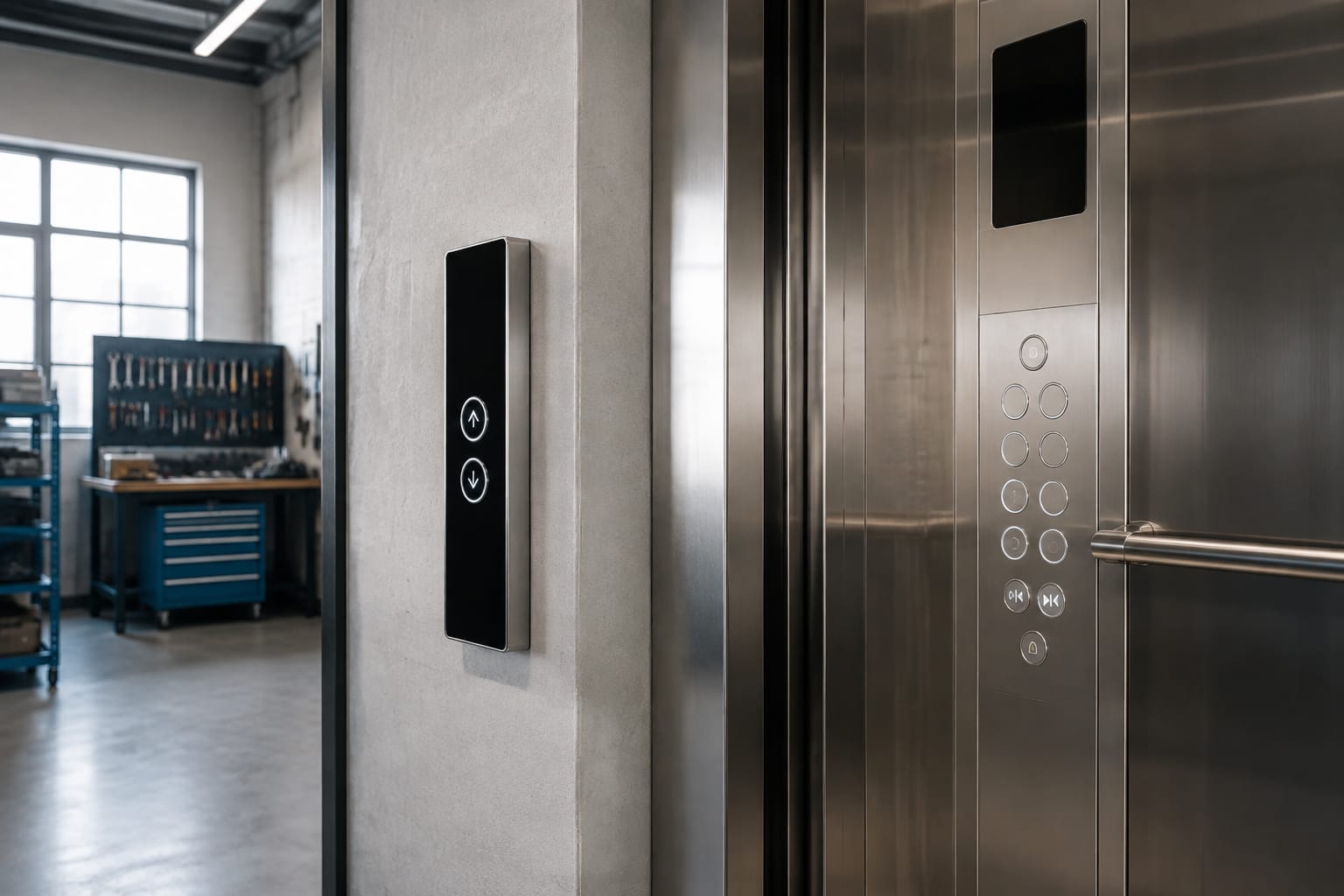
Replacing Schindler buttons is not a matter of matching the visible face alone. A correct replacement must suit the panel position, controller or board family, physical cut-out, mounting method, illumination arrangement and electrical connector. Record these details before removing the existing unit, especially where the lift is still in service and the original part number is unavailable.
For Indian maintenance contractors and sourcing teams, the most reliable approach is to treat the button and its supporting board as a matched assembly. A similar-looking car operating panel (COP) or landing operating panel (LOP) button may fit the opening but still fail to illuminate, register calls incorrectly or communicate with the panel electronics.
Schindler COP and LOP button functions
Schindler buttons are generally installed either inside the lift car or at a landing. The function and panel environment determine what must be matched.
A COP button is installed in the car operating panel. It can include:
- Floor-selection buttons
- Door open and door close buttons
- Alarm or emergency call buttons
- Fan, light or service-control buttons
- Car-call indication and confirmation illumination
- Floor displays or integrated touch interfaces
An LOP button is installed outside the lift car, typically as an up, down or combined hall-call control. Depending on the installation, the landing panel may also contain a display, direction arrows, key switch or access-control arrangement.
The distinction matters because a car-call button and a hall-call button are not interchangeable merely because their symbols look alike. They may use different boards, signalling logic, illumination states and mounting arrangements.
Before ordering, write down whether the failed item is in the COP or LOP, its exact location, and its function. For example, record “LOP, down call, first-floor landing” rather than simply “Schindler down button”. This avoids ordering a compatible-looking but functionally incorrect component.
What to record from the panel
Photograph the complete panel before dismantling it, then take close images of the failed button, rear connector and any printed circuit board markings. The useful record includes:
- Lift car panel or landing panel
- Floor served and call direction, where relevant
- Button function and visible symbol
- Number of buttons or display modules in the panel
- Model or equipment family shown on labels
- Board code, revision and manufacturer marking
- Button face dimensions and panel cut-out dimensions
- Connector type, pin count and cable orientation
- Illumination colour and confirmation behaviour
- Whether the unit is a mechanical push button or touch interface
A panel-wide photo is particularly useful for sourcing teams. It gives context that a close-up cannot: button spacing, display position, faceplate style and whether modules are part of a shared board.
Identify 3300 and 3600 applications
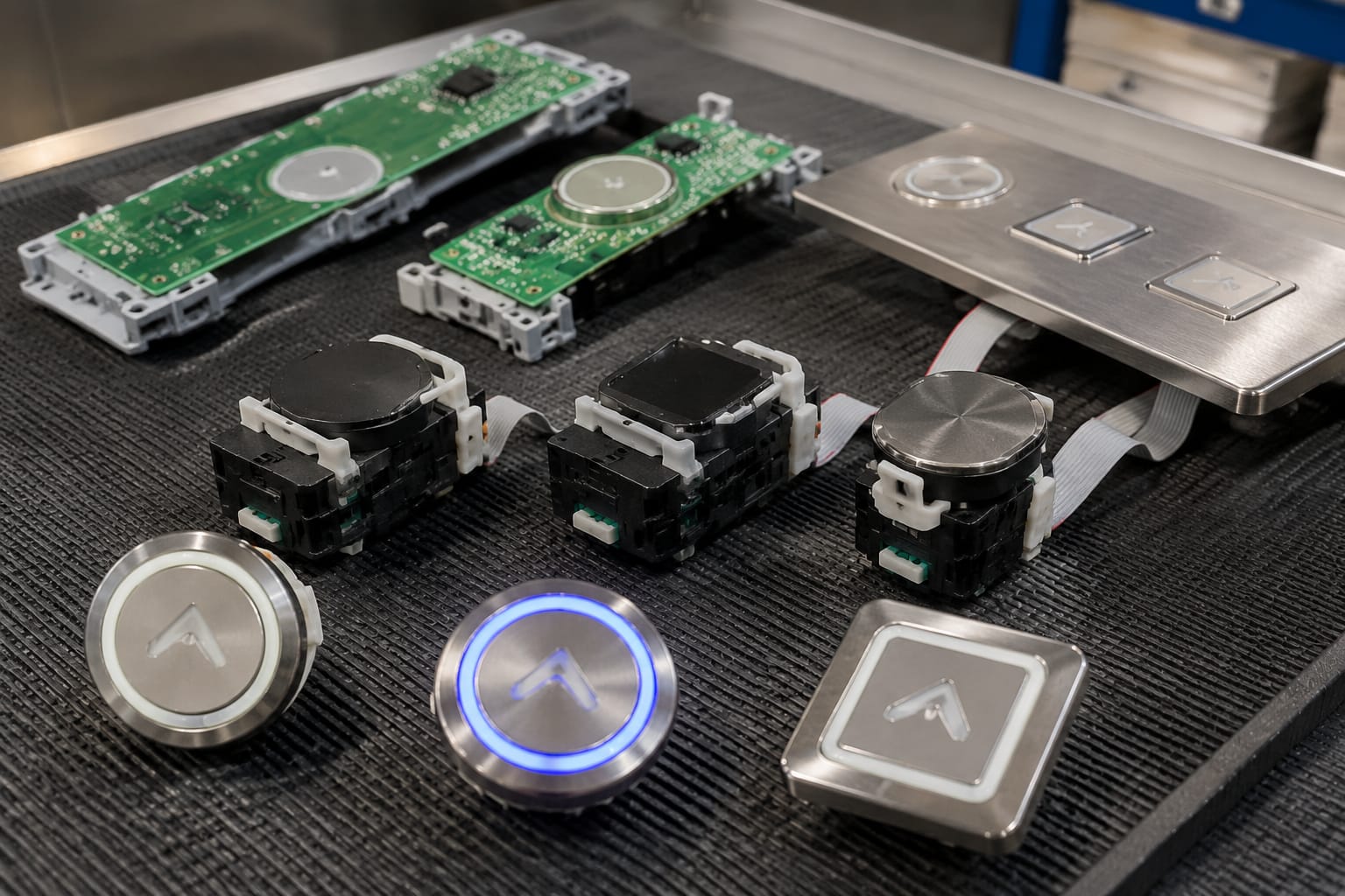
The Schindler 3300 and 3600 names are frequently used in replacement-part enquiries, but the model-family name alone is not enough to establish compatibility. Over a product lifecycle, panels can use different revisions, button assemblies and boards. Modernisation work may also have introduced newer components into an older installation.
Use the model family as a starting point, then verify the actual panel hardware.
For 3300 and 3600 applications, inspect the board behind the call button or touch surface. The printed board code and connector layout usually provide stronger evidence than the front-face design. A board intended for one panel arrangement may look nearly identical to another but have a different connector position, number of contacts or signal configuration.
Where the failed component is a hall-call assembly rather than an individual button, compare it with the relevant product category. For example, an [ID hall-call button board for 3600 and 3300 lifts](/products/3600-3300-elevator-hall-call-button-board-id-lift-parts/) may be relevant only after confirming that the board code, panel role and connector arrangement correspond to the installed unit.
Do not infer compatibility from the landing appearance
A building may have matching stainless-steel panels throughout, while different landing boards are installed across lift banks, entrances or later modernisation phases. Likewise, car panels in the same building can differ between cars.
Check each failed position individually when:
- The panel has been repaired before
- A lift has undergone partial modernisation
- Board labels differ between floors or cars
- The replacement is for a display-and-button assembly
- The existing part has no readable label
- The panel uses touch-sensitive controls
If an existing part has a Schindler identification label, record the complete code exactly, including suffixes, revision marks and barcode text where legible. Do not omit letters or assume a revision is irrelevant.
Compare push and touch buttons
Schindler buttons can be conventional mechanical push buttons or touch-based controls. They should be assessed differently during fault diagnosis and replacement.
| Checkpoint | Mechanical push button | Touch button or touch board |
|---|---|---|
| User action | Physical press with travel or tactile response | Contact or proximity action on a touch surface |
| Common fault signs | Sticking, broken cap, weak return, intermittent contact | Unresponsive zone, erratic response, cracked surface, board fault |
| Replacement scope | Individual button, lamp, contact block or assembly may be replaceable | Often supplied as a board or integrated module |
| Main compatibility checks | Cut-out, clip or nut fixing, terminals, lamp or LED arrangement | Board code, firmware-dependent arrangement where applicable, connector, mounting and face layout |
| Testing focus | Call registration, release action, illumination and adjacent buttons | Correct touch detection, display response, call registration and communication stability |
A push button should not be replaced with a touch module simply because the face dimensions are similar. The panel construction and electronics may not support it. The reverse is equally true: a mechanical replacement will not substitute for a touch-board input.
For a touch-based panel, inspect whether the failed area is an individual touch key, a shared button board or a wider display assembly. If the controls form part of one board, replacing only the visible surface may not solve a fault caused by the electronics underneath. Confirm the board identification against the existing hardware before selecting a replacement such as an [ID touch button board for 3300 and 3600 lift panels](/products/id-touch-button-board-3300-3600-elevator-parts/).
Diagnose before ordering
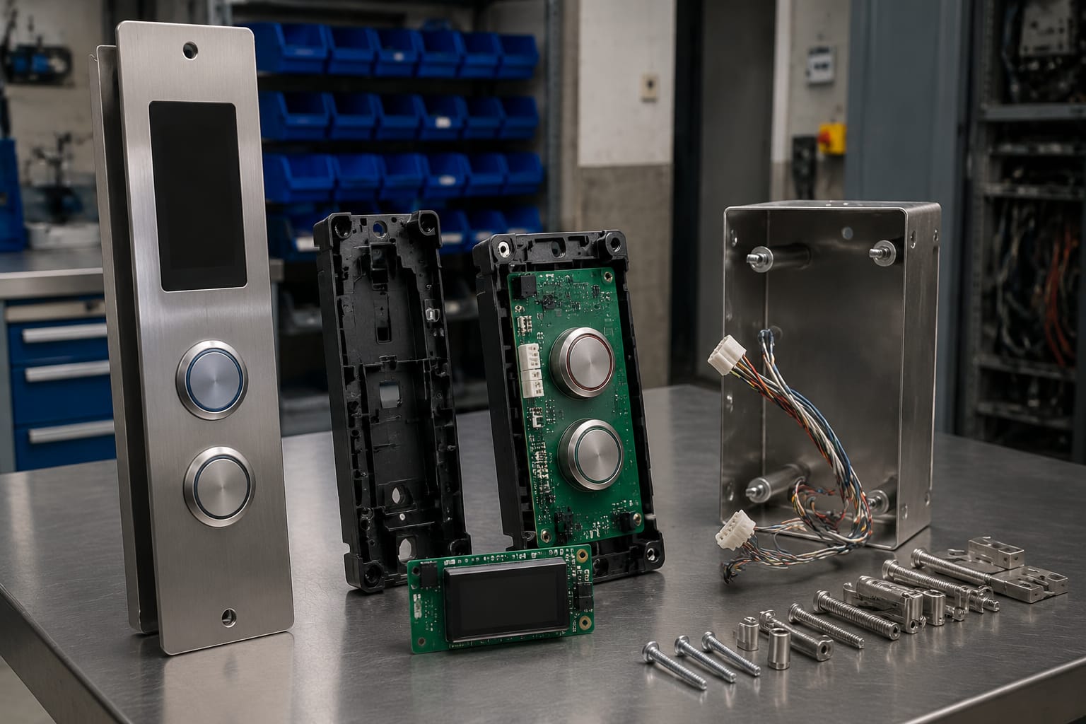
A non-working button does not always mean that the button itself has failed. Before replacement, a qualified technician should consider:
- Loose, damaged or corroded connectors
- Harness damage near the hinge, panel edge or cable route
- A failed LED or illumination circuit
- Incorrect panel supply voltage
- A board-level fault affecting several keys
- Moisture ingress or cleaning-product residue on touch surfaces
- A controller or communication fault
When multiple controls fail together, investigate the shared board, power supply and harness first. Ordering several individual Schindler buttons may not address the underlying problem.
Match dimensions and mounting
Dimensions are among the most common causes of an unsuccessful replacement. Measure both the button assembly and the panel opening; neither measurement on its own is sufficient.
Use a vernier caliper where practical and note measurements in millimetres. Record:
- Visible face width and height, or diameter for round buttons
- Depth behind the panel
- Panel cut-out width and height, or diameter
- Mounting-hole spacing for boards and modules
- Distance from button edge to retaining clips or fixing points
- Panel thickness, if the mounting design depends on it
- Clearance behind the panel for connectors and cables
A replacement can have the same visible size but a different rear housing, preventing the panel from closing. Conversely, a unit may fit behind the panel but leave an exposed gap around the face.
Confirm the mounting method
Schindler button assemblies can be secured through clips, retaining rings, screws, studs or a board-mounted arrangement. Identify the method before dismantling the existing part.
Do not force clips from the front of a finished stainless-steel panel. This can bend the faceplate, damage the button bezel or mark the surface. Follow the panel’s approved access procedure and isolate the lift equipment before work begins.
For shared boards, measure mounting-hole centres and compare the position of displays, icons and apertures. A board that has the same external size but misaligned mounting points is not a direct replacement.
Check illumination and symbols
Illumination is part of the button specification, not just a cosmetic preference. A button may have standby lighting, confirmation lighting after a call is registered, directional lighting, or multiple colours for different operating states.
Record the illumination details from the installed Schindler button:
- Light colour when idle
- Light colour after a valid call
- Whether the symbol, ring, border or full face illuminates
- LED or other lighting arrangement, where identifiable
- Brightness consistency with adjacent buttons
- Whether illumination is integrated into the button or supplied from the board
Avoid selecting a replacement based only on an online image. Product photos may not show the illuminated state, rear connector or revision-specific symbol layout.
Symbols also need exact matching. A door-open icon, door-close icon, alarm symbol, bell, phone icon, accessibility marking and floor label may use different graphics. For LOPs, verify up, down and combined-direction symbols. A symbol that is visually close but functionally wrong can create a safety and usability issue.
If the replacement is intended for a public-facing panel, inspect the finished result for alignment, legibility and consistent illumination. A technically working button that sits unevenly or has a mismatched symbol degrades the panel and can confuse passengers.
Verify board codes and connectors
The board code is usually the most valuable compatibility reference for a board-mounted or touch-based replacement. Record every visible code from both sides of the board before removing it. Include the revision number and any labels on the harness.
A matching board code does not remove the need to verify the connector, but it substantially reduces ambiguity. Where the code differs, compare official technical documentation or obtain confirmation based on the complete set of recorded details.
Connector checks that prevent misorders
Compare the following against the installed item:
- Connector family and housing shape
- Number of pins and populated positions
- Pin orientation and locking feature
- Cable-entry direction
- Number of connectors on the board
- Wire colours and harness labels, as supporting evidence only
- Presence of jumpers, switches or additional terminals
- Connector clearance after installation
Never modify a connector, cut a harness or force a plug to make a replacement fit. Similar housings can have different pin assignments. A forced connection can damage the board or cause incorrect operation.
For touch hall-call applications, inspect the relationship between the board, display aperture and surrounding faceplate. A [3300 touch hall-call button display board](/products/3300-touch-hall-call-button-display-board-elevator-parts/) should be selected only where its board identification, mounting and connector arrangement correspond to the installed panel.
Test the panel after replacement
Replacement work is incomplete until the panel has been functionally tested. Test under controlled conditions by authorised personnel and in accordance with the site’s maintenance procedures.
For a COP button, confirm that the button:
- Sits flush and is securely mounted.
- Registers the intended floor or function.
- Provides the expected illumination or call confirmation.
- Does not cause unintended calls or repeated registration.
- Allows adjacent buttons to operate normally.
- Does not interfere with panel closure, wiring or service access.
For an LOP button, test calls from the relevant landing and verify that the intended direction registers. Confirm that any display, arrow or acknowledgement indication remains correct. Test both directions where the landing panel provides separate up and down calls.
After the initial test, check for intermittent operation. Press the button repeatedly, inspect illumination in normal ambient conditions, and verify that cables remain seated after the panel is reassembled.
Common post-replacement faults
The most frequent issues after a replacement are usually compatibility or installation errors:
- Button fits but has no illumination
- Button illuminates but does not register a call
- Call registers only intermittently
- Touch area responds incorrectly or needs repeated contact
- Adjacent controls stop functioning after reassembly
- Board connector is partly seated or cable is trapped
- The panel face is stressed because rear clearance was not checked
- An incorrect symbol or direction button has been installed
When a newly fitted part behaves unexpectedly, stop repeated testing and recheck the board code, connector seating, harness orientation and panel function. Do not assume the replacement is defective before eliminating an application mismatch.
Button sourcing checklist
Use this checklist when requesting or evaluating Schindler buttons for replacement:
- [ ] COP or LOP location identified
- [ ] Lift model family recorded, including 3300 or 3600 where applicable
- [ ] Complete existing part number or board code captured
- [ ] Clear front and rear photographs available
- [ ] Button function and symbol confirmed
- [ ] Push-button or touch-board construction identified
- [ ] Face size, cut-out and rear depth measured in millimetres
- [ ] Mounting method and fixing-point spacing recorded
- [ ] Illumination colour and behaviour noted
- [ ] Connector shape, pin count and orientation verified
- [ ] Number of buttons, displays and modules in the panel recorded
- [ ] Evidence checked for previous panel repairs or modernisation
- [ ] Functional testing plan prepared after installation
For B2B procurement, send the checklist with photographs rather than relying on a description such as “Schindler lift button”. It gives a distributor, importer or spare-parts supplier enough information to compare the required item against available references and flag uncertainty early.
Kelevator supplies multi-brand elevator spare parts for B2B importers, distributors, maintenance contractors and OEM buyers. When sourcing a Schindler replacement, provide the panel and board details above so the component can be assessed against the actual application rather than appearance alone.