
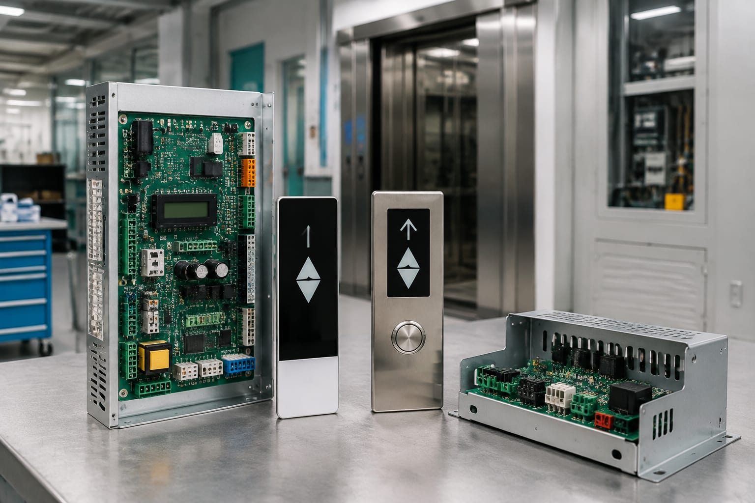
Schindler parts should be identified from the installed equipment, not from the component’s appearance alone. A board, display or door controller may look similar across installations, yet differ in software revision, connector arrangement, supply requirements or communication method. The most reliable order record combines the equipment family, original label details, clear photographs and the application within the lift.
For maintenance and modernisation work in India, begin by matching the failed component to the controller or door system already on site. Then check the board code, revision, connector layout, voltage markings and cables before approving a replacement. This reduces the risk of receiving a part that physically fits but cannot operate correctly in the installation.
Identify the Schindler equipment family
The equipment family is the first compatibility filter for Schindler elevator parts. It establishes where the component sits in the lift system and which surrounding equipment it must work with. Do not assume that the lift car or landing fixture style alone confirms the family; modernised installations may retain some original fixtures while replacing other equipment.
Start with the following information from the site:
- Lift controller model and cabinet labels
- Door operator make, model and controller details
- Car operating panel and landing display references
- Existing component part number and revision
- Lift serial or installation reference where available
- Clear photographs of the installed item, both sides and all connectors
- The fault report or observed behaviour
A component’s location matters as much as its part number. For example, a board inside the main controller may handle safety-chain inputs, drive control, communication or input/output functions. A visually similar board in the car operating panel may be intended only for display, button inputs or car communication.
When the original item is unreadable or missing, use a structured identification process. Photograph the controller interior without disturbing wiring, record connector positions, count terminals and note cable markings. Also confirm whether the lift is a passenger lift, goods lift, hospital lift or another application, since configuration can affect the parts installed.
Avoid ordering by generic descriptions such as “Schindler lift card” or “Schindler display board”. These descriptions are too broad to establish fit. A supplier can assess options more accurately when the equipment family and original board label are included.
Common control and door components
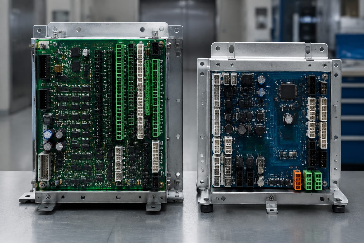
Schindler parts cover several functional groups. Understanding the role of a component helps maintenance teams collect the right information and distinguish a likely substitute from an unrelated item.
| Component group | Typical function | What to identify before ordering |
|---|---|---|
| Main controller board | Processes lift operation, inputs, outputs and system logic | Cabinet model, board code, revision, software or label information, all plug positions |
| Input/output board | Connects controller logic to field devices and signals | Terminal count, connector type, I/O marking, voltage reference and location in cabinet |
| COP display board | Controls floor indication, direction arrows, messages or button-interface functions in the car | Display type, panel reference, connector layout, mounting dimensions and cable count |
| Landing display module | Provides floor and direction information at a landing | Fixture model, display format, wiring connection and mounting arrangement |
| Door operator controller | Controls door motor movement, opening and closing logic, and door signals | Door operator model, motor connection, supply information, encoder or sensor connections |
| Power supply module | Provides power to boards, displays or related circuits | Input/output ratings, mounting method, terminal layout and any fuse arrangement |
| Encoder or sensor interface | Receives position or movement signals from mechanical equipment | Sensor type, connector pinout, cable length and associated controller family |
A failed part is not always the root cause. A door controller fault, for example, can be caused by worn mechanical door components, damaged travelling cable cores, poor earthing, supply irregularities, motor defects or a problem in the controller signals. Replacing the controller without verifying these conditions can create repeat failures.
Similarly, display issues may arise from the display board, panel wiring, car communication connection or the main controller configuration. Inspect connectors for looseness, heat marks, corrosion, bent pins or damaged locking tabs before classifying the board as defective.
For control and display replacements associated with the relevant lift family, compare the original labels against the details on available 3300/3600 elevator control boards and 3300/3600 COP display boards. Product category names are useful starting points, but the label-level comparison remains essential.
Read board labels and part codes
The original label is usually the strongest evidence for selecting Schindler replacement parts. Record every line exactly as shown, including prefixes, suffixes, spaces, hyphens and revision identifiers. A minor character difference may indicate a different hardware issue, board generation or approved application.
Look for the following on the component:
- Manufacturer or equipment branding
- Printed circuit board number, often printed directly on the PCB
- Part number or material number on a sticker
- Revision, issue, version or index code
- Manufacturing batch or serial reference
- Firmware, software or configuration label where present
- Voltage, polarity and current markings
- Connector designations, such as CN, X, J or terminal reference markings
A sticker part number and a PCB number may not be identical. The sticker can identify the saleable assembly, while the board printing identifies the bare circuit board design. When both are available, provide both. This is particularly important if an assembly includes programmed memory, relays, heat sinks, display modules or mounting hardware that may not be part of the bare board reference.
Photograph labels for useful comparison
Take close, readable photos in good light. Include:
- The front of the complete component.
- The rear or solder side where practical and safe.
- Every label and printed board reference.
- Each connector and terminal strip.
- The installed location before cables are disconnected.
- Any visible damage, overheated area or missing part.
Do not rely on a photograph taken from a distance inside the controller cabinet. It may show board colour and shape but not the details needed to confirm an exact match.
Treat cross-references carefully
A supplier may describe a compatible replacement or a superseded reference. That does not automatically mean it is interchangeable in every lift. Ask what the cross-reference is based on and whether it covers the same application, connector arrangement, power supply and communication requirements.
Where an original part number has been replaced by another reference, verify whether installation requires parameter transfer, firmware programming, harness changes or additional components. A cross-reference without this context is incomplete.
Compare 3300 and 3600 applications
Schindler 3300 and 3600 references are often discussed together in the spare-parts market, especially for selected control and car-panel electronics. They should still be treated as separate applications until the original component data shows a confirmed match.
The practical question is not whether a part is marketed for “3300/3600”, but whether it matches the exact installed controller, panel or door arrangement.
| Check point | Why it matters for 3300 and 3600 applications |
|---|---|
| Original board code | Similar product families can use different board references or revisions |
| Cabinet location | A board from the main controller may not match a car or landing application |
| Connector positions | Plug headers may differ in count, orientation, keying or pin allocation |
| Panel layout | Car operating panels can vary by display format, buttons and communication connection |
| Software/configuration | A replacement may need compatible firmware or site-specific configuration |
| Door equipment | Door controller compatibility depends on the operator, motor and feedback connections |
| Mounting hardware | Board dimensions, fixing holes and heat-sink clearance can prevent installation |
For example, a control board listed for a 3300/3600-related application must still be checked against the actual board reference and cabinet connections. Do not accept a match based only on the lift model stated verbally by the building representative. Site documentation can be incomplete, and an earlier repair or modernisation may have changed the installed assembly.
Door equipment deserves the same care. The door operator controller must correspond to the installed operator and its motor, sensors and harness. Review the information available for a 3300 door operator controller only alongside the controller label and physical connections from the site.
Check revisions and connectors
Revision differences are one of the most common reasons that an apparently identical board fails to fit or function. The revision may reflect changes to components, connector allocation, firmware support, electrical protection or manufacturing updates. It can be harmless, required for compatibility or a reason to reject the part, depending on the application.
Record the revision in the same way you record the base part number. Examples of revision labels include “Rev”, “Ver”, “Issue”, “Index” or a letter-number suffix. Never omit this information from an enquiry merely because the base number matches.
Compare connectors systematically
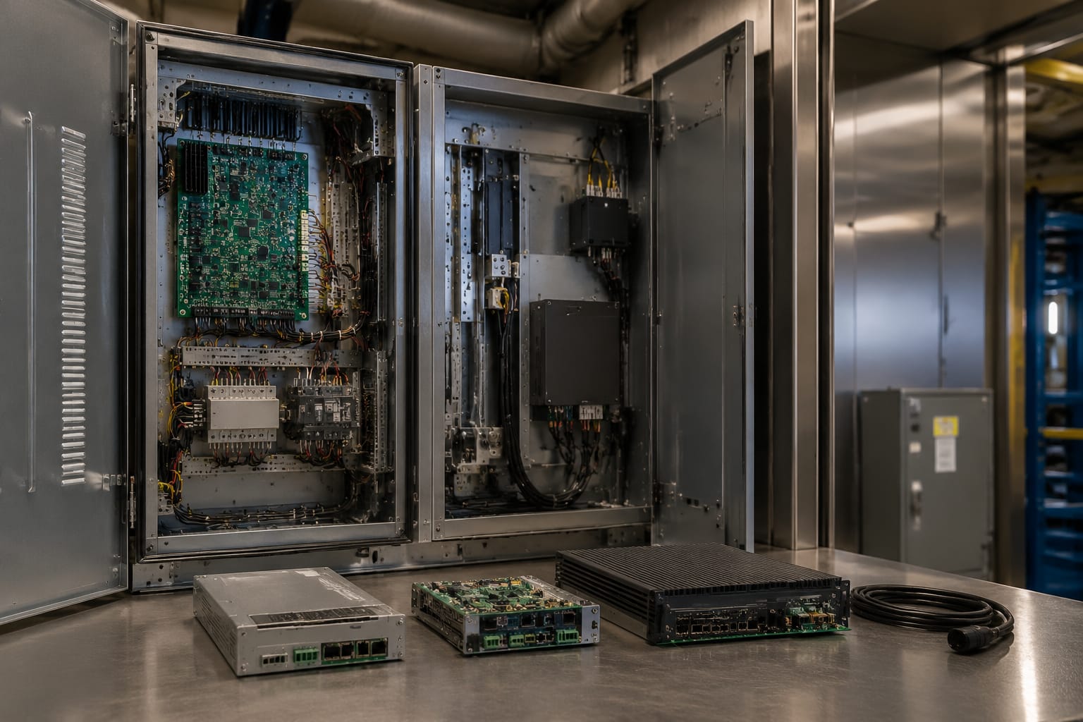
Before ordering, compare the original and proposed replacement in a fixed sequence:
- Number of connectors and terminals
- Connector family, gender and physical keying
- Position and orientation of every connector
- Pin count and visible pin arrangement
- Label next to each connector
- Ribbon cable direction and latch style
- Screw-terminal numbering and spacing
- Board edge shape, fixing-hole positions and component clearance
A connector that plugs in physically may still use a different pin allocation. Do not move plugs between boards based on position alone. Use original wiring records, component markings and qualified technical verification where the function is safety-related or uncertain.
For boards mounted near metalwork or other electronics, also compare height and heat-sink clearance. A replacement that touches the cabinet, cover or adjacent board may create an electrical or heat-management risk.
Confirm voltage and communication details
Electrical compatibility must be verified before a Schindler part is fitted. Check the markings on both the original component and its associated equipment. The system voltage, board supply voltage and signal voltage are not necessarily the same.
Confirm these details:
- Incoming supply rating and whether the board uses AC or DC
- Voltage range, polarity and terminal designation
- Current or power requirement where marked
- Earthing connection and mounting arrangement
- Fuse type and rating where applicable
- Motor output requirements for door controllers
- Sensor, encoder or limit-switch connections
- Communication port type and connector
- Any bus or network labels shown on the board or cable
Communication compatibility can be less visible than physical compatibility. A car display board may have the correct mounting dimensions and connector count but use a different signalling arrangement. In that situation, it may power on without delivering correct floor indication or button operation.
Do not infer a communication protocol solely from wire colours. Cable colours can vary across installations and repairs. Use connector labels, wiring diagrams and the original equipment records where available.
For controllers and door systems, work should be performed by suitably qualified personnel following the applicable site procedures. Lift equipment contains safety-critical circuits. A board replacement should not bypass protective circuits, alter wiring logic or be treated as a substitute for fault diagnosis.
Evaluate supplier documentation
The quality of supplier documentation determines how confidently a sourcing team can assess a proposed part. A useful supplier response should help you compare the offer to the installed unit rather than asking you to rely on a broad model claim.
Request documentation appropriate to the component and purchase stage:
- Product photos showing labels, connectors and mounting points
- Exact offered part number and revision, where available
- Clear condition description for the supplied item
- Compatibility basis, including the equipment family or original reference compared
- Dimensions or mounting information when fit is uncertain
- Connector photos or pin details where layout is critical
- Information on included accessories, such as heat sinks, covers, cables or fasteners
- Commercial terms, inspection process and return conditions before ordering
For a replacement described as compatible rather than original, ask whether the part is a direct functional equivalent, an adapted solution or a component requiring modification. “Compatible” alone is not a technical specification.
B2B buyers should also preserve a traceable internal record: site name or asset code, lift identification, failed-part photographs, original reference, proposed replacement reference, approval notes and installation outcome. This makes repeat purchasing more efficient and prevents the same uncertainty when another lift requires a similar component.
Kelevator supplies multi-brand elevator spare parts to B2B importers, distributors, maintenance contractors and OEM buyers. For a technical enquiry, the most useful submission is a complete identification pack rather than only a generic product name.
Final sourcing checklist
Use this checklist before issuing a purchase order for Schindler parts:
- [ ] Confirm the installed equipment family and component function.
- [ ] Record the original assembly part number and PCB number.
- [ ] Capture the revision, version or index identifier.
- [ ] Photograph front, rear, labels, connectors and installed location.
- [ ] Compare connector count, keying, orientation and pin arrangement.
- [ ] Verify mounting dimensions, fixing holes and clearance.
- [ ] Confirm incoming supply, board voltage, polarity and relevant motor or sensor connections.
- [ ] Check communication and cable-interface details.
- [ ] Establish whether the offered item is original, replacement, compatible or superseded.
- [ ] Confirm what is included with the offered component.
- [ ] Review whether programming, configuration or commissioning is required.
- [ ] Retain the approval record and installation result for future maintenance.
The safest sourcing decision is evidence-based: match the original label first, then validate physical fit, electrical requirements and communication details. Where any of these cannot be confirmed, treat the part as unverified rather than assuming that a similar-looking board will work.
For an accurate B2B quotation or technical comparison, provide the original Schindler part details, equipment family, installation photographs and connector images to Kelevator or the selected supplier.
Related product references
For practical catalog examples related to this topic, review [3300 3600 Elevator Control Board ID lift parts](/products/3300-3600-elevator-control-board-id-lift-parts/), [3300 3600 Elevator COP Display Board ID lift parts](/products/3300-3600-elevator-cop-display-board-id-lift-parts/), and [Door Operator Controller 3300 elevator parts](/products/door-operator-controller-3300-elevator-parts/). Confirm the exact model, dimensions, ratings, and connectors before ordering.