
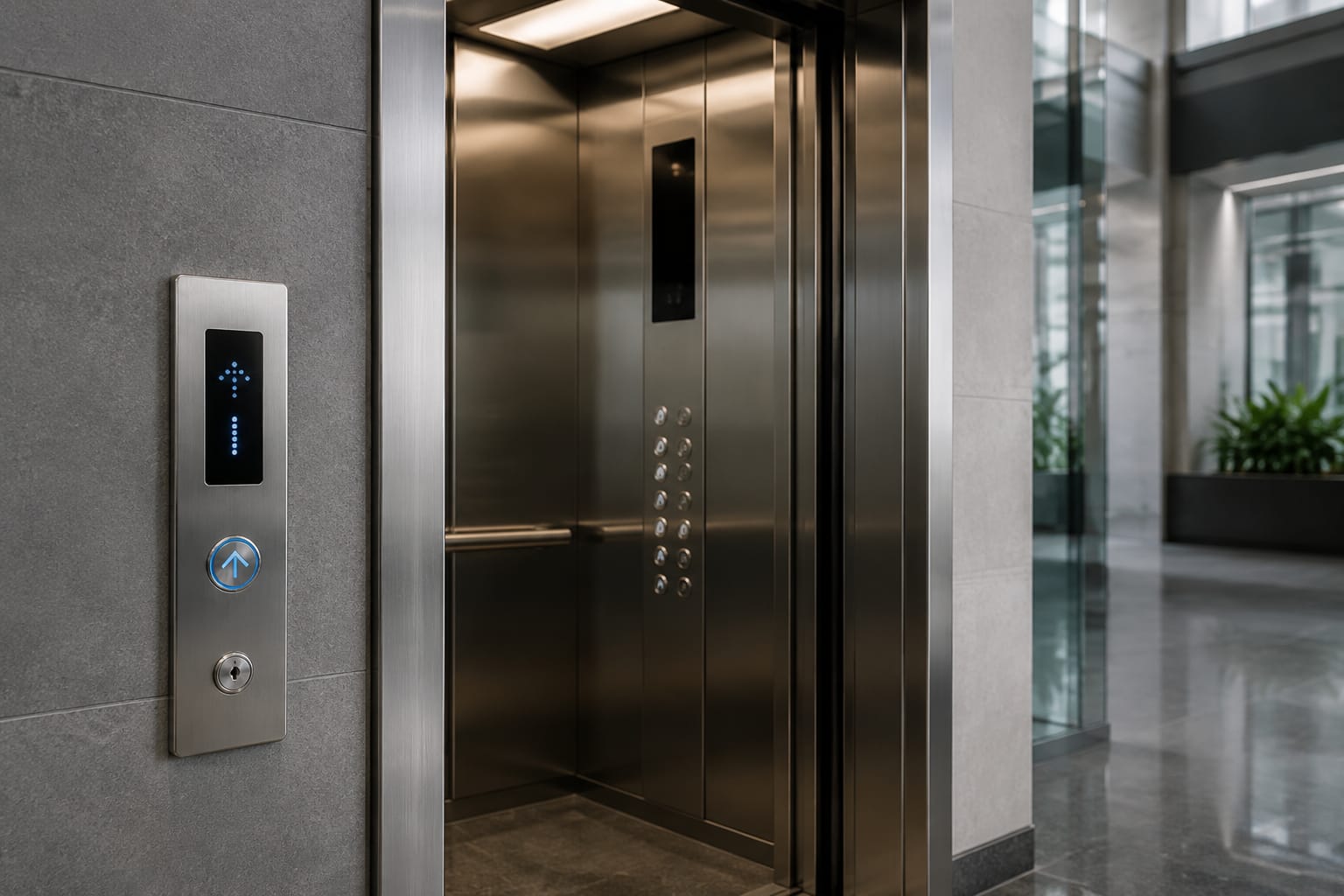
ThyssenKrupp elevator buttons cannot be selected reliably from their visible shape alone. A replacement may look similar yet fail because its cutout size, pin arrangement, voltage, illumination method, controller interface or mounting depth differs. The most dependable approach is to document the installed button or board together with the panel, wiring and controller details before requesting a quotation.
For maintenance teams and sourcing buyers, the objective is not merely to find a matching-looking push button. It is to establish whether the part is an exact replacement, a compatible substitute requiring minor panel work, or a modernization item that needs changes to wiring or logic. This guide sets out the information needed to make that decision.
Car and landing button locations
Start by identifying where the required ThyssenKrupp elevator button is fitted. Car operating panel (COP) buttons and landing operating panel (LOP) buttons can use different constructions even when their faceplates share a similar design language.
Car operating panel buttons
Inside the lift car, document every relevant control rather than only the failed button. Typical COP controls include:
- Floor-selection buttons
- Door open and door close buttons
- Alarm or emergency call button
- Fan, light or attendant controls where fitted
- Key switch positions
- Emergency stop controls in applicable installations
- Position indicator and direction arrows
- Braille or raised-symbol markings
A floor button may be supplied as a complete assembly comprising the cap, retaining ring, lamp or LED module, microswitch and harness connection. In other panels, only the cap or contact block may be replaceable. Photographing the front and rear of the assembly helps establish which construction is installed.
Landing call buttons
At a landing, record whether the station is:
- A single up-call station
- A single down-call station
- A two-button up/down station
- A destination-control terminal
- A combined call station and display
- A fire-service, key-operated or restricted-access station
Landing buttons are often supplied as part of a call board, particularly in compact or flush-mounted designs. Replacing an individual button on a board may not be practical if the switch, LED and logic are integrated on the PCB. In that case, board identification is more important than the visible button dimensions.
Why location changes the sourcing decision
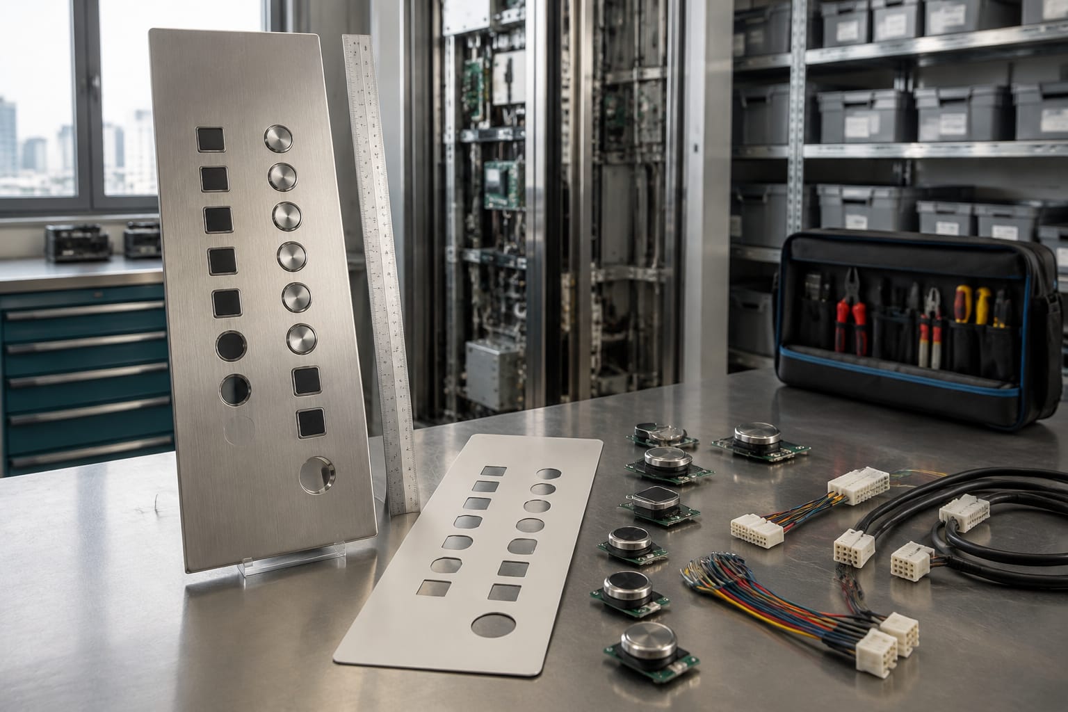
A car button generally needs compatibility with the COP wiring and button circuit. A hall-call button may need to communicate with a landing board, display module or serial network. Therefore, a “ThyssenKrupp lift button” enquiry should always state whether the item is for the car, landing, machine-room station or another location.
Identify the panel and controller family
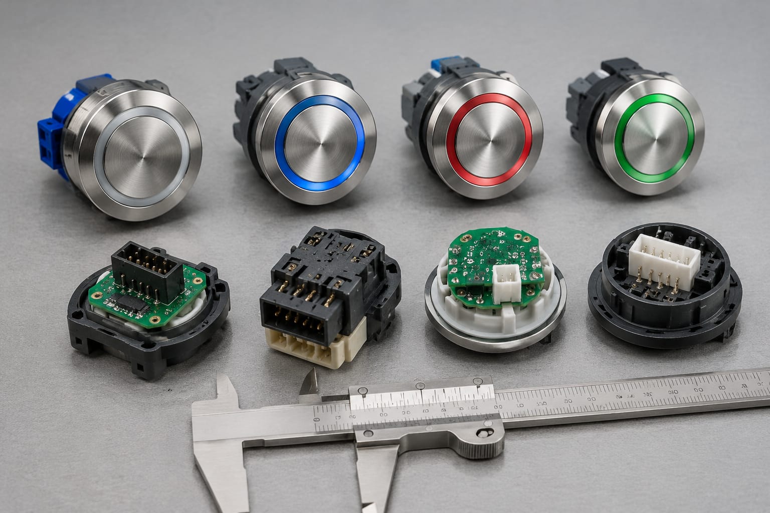
The button is one part of a larger electrical system. Record the panel type and controller information before deciding that a visually similar component is suitable.
Look for identification labels in these places:
- Rear of the COP faceplate or inspection opening
- Back of the landing panel
- Inside the controller cabinet
- On the call-board PCB
- On display modules and harness labels
- In maintenance records, wiring drawings or modernization documents
Capture the complete wording on labels, including prefixes, suffixes, revision levels and date codes. A partial part number can lead to an incorrect match because revised boards may use different connectors or firmware.
Details to record from the controller
For a controller-related button or call-board enquiry, note:
| Detail | Why it matters |
|---|---|
| Controller make, model and serial details | Helps determine the system family and communication method |
| Number of stops and door configuration | Can affect display programming and call-board application |
| COP or LOP designation | Separates car controls from landing-call components |
| Existing board part number and revision | Identifies electrical and physical variants |
| Wiring diagram reference | Helps verify terminals, supply and signal paths |
| Whether the lift has been modernised | Original panel parts may no longer match the current controller |
Do not assume that the controller brand name alone proves compatibility. Installations may have had replacement COPs, upgraded boards or retrofitted controllers over their service life. The installed part number and wiring arrangement remain the stronger evidence.
Panel style is useful, but not conclusive
Panel photographs can help suppliers narrow down the likely family. Take a straight, well-lit photo of the entire panel as well as close-ups of buttons, displays and engravings. However, panel styling should be treated as a clue, not as confirmation. Different projects may use similar stainless-steel panels with different electronics behind them.
For projects needing a non-standard replacement panel, review the available options for [custom elevator car operating panels, buttons and displays](/products/elevator-car-control-panel-car-button-display-cop-customization/). A custom panel can be relevant when an exact cosmetic replacement is unavailable, but its electrical integration must still be assessed.
Measure button and cutout dimensions
Measurements determine whether a replacement fits the panel without cutting, drilling or changing the mounting arrangement. Measure the existing part after isolating power and following the site’s authorised maintenance procedure.
Use a vernier caliper where possible. A tape measure is often insufficient for small differences in button diameter and panel cutouts.
Essential dimensions
Record the following in millimetres:
- Visible face diameter, width and height
- Panel cutout diameter or rectangular aperture size
- External bezel dimensions
- Overall depth behind the panel
- Mounting collar or thread diameter
- Retaining nut dimensions where applicable
- Distance between fixing holes for plate-mounted assemblies
- PCB dimensions for integrated call boards
- Connector position relative to the board edge
For square or rectangular buttons, measure width and height separately. For circular buttons, measure the aperture and bezel diameter separately. A button with a larger bezel can cover the opening but still fail to mount if the rear collar is incorrect.
Check panel thickness and rear clearance
Panel thickness affects how a button locks into place. Also inspect the space behind the panel for harnesses, structural members, display boards or adjacent switches. A deeper replacement may foul another component even when its front dimensions match.
For a replacement involving a new panel faceplate, measure the full panel width and height, corner radii, fixing points, inspection openings and cutouts for indicators or key switches. This reduces the risk of receiving a panel that cannot be installed without site modification.
Common measurement mistakes
The most frequent sourcing errors are:
- Measuring the button cap but not the panel cutout
- Sending dimensions without specifying units
- Omitting button depth
- Measuring a worn or loose bezel instead of the mounting body
- Ignoring the position of locating tabs or anti-rotation flats
- Assuming all buttons on the same panel use identical bodies
- Sending photographs taken at an angle, which distort apparent dimensions
A simple labelled sketch beside the photos can prevent ambiguity. Mark the front view, side view, cutout and connector location.
Check illumination and tactile features
Illumination, markings and tactile features are functional requirements, not merely appearance details. Record them carefully when identifying ThyssenKrupp elevator buttons.
Illumination requirements
Confirm:
- Whether the button is illuminated at rest, on registration, or both
- Illumination colour before and after a call is registered
- LED, lamp or light-guide construction
- Supply voltage and polarity, where identifiable
- Whether the lamp or LED module is replaceable separately
- Whether the button uses a common supply or board-controlled illumination
- Any flashing pattern for alarm, fire or special-service functions
A two-colour or status-controlled button cannot necessarily be replaced with a single-colour illuminated button. Likewise, a standalone lamp assembly may not substitute for an LED controlled directly by a landing board.
Tactile markings and legends
Document the button legends exactly:
- Numerals, letters and floor labels
- Basement, parking, terrace or special-floor symbols
- Door open, door close, alarm and bell symbols
- Braille dots and their placement
- Raised numerals or raised icons
- Engraved, printed or laser-marked legends
- Arrow orientation for up and down calls
In Indian projects, floor naming can vary considerably, such as B2, LG, G, P, M, 1 or T. Do not rely on a supplier to infer the required legend from a floor count. Provide a panel schedule or clear list of every label needed.
Colour, finish and visual consistency
Where the building requires a consistent appearance, note the button face finish, ring colour, panel finish and LED colour. Differences in chrome tone, stainless-steel grain direction, black coating or icon style can be noticeable after repair, especially on premium or recently modernised installations.
However, cosmetic matching should not override electrical suitability. A compatible button with a different finish may be an acceptable maintenance decision in some sites, while other sites may require a matched complete set.
Record board codes and connectors
For integrated landing call boards, display boards and button PCBs, the board code is usually the most valuable sourcing detail. Photograph both sides of the PCB before removal if access permits.
Board information to capture
Record or photograph:
- Full PCB part number
- Revision number, such as
REV,R,Vor a date revision - Manufacturer marking
- Barcode and serial label
- Board dimensions
- Connector references printed on the PCB
- Switch, LED, relay or terminal designations
- Number and colour of connected cables
- Jumper or DIP-switch settings
- Fuse or component labels where visible
The revision number matters. A board with the same base part number but a later revision may have altered pin assignments, display support or software behaviour.
Connector identification
Take close-up images of every connector with the plug still connected, followed by images with the plug removed where it is safe and authorised. Include the wire colours, terminal labels and keying features.
Check:
- Pin count
- Single-row or double-row format
- Connector pitch and locking method
- Orientation notch or polarisation key
- Plug position on the board
- Wire harness part number, if labelled
- Screw terminal versus plug-in connector
- Daisy-chain or bus in/out connections
Do not select a board based only on connector pin count. Two eight-pin connectors may use different pitch, keying and signal assignment. Forced connection can damage the board or wiring harness.
Evaluate display and call-board integration
Display modules and call boards may be independent components, but many installations combine them into a shared assembly. Establish the relationship before ordering a replacement.
Questions to answer
- Does the landing display share the same PCB as the call buttons?
- Is the display connected by a separate harness or a common board connector?
- Does the board serve one landing only or several landings?
- Is the display a simple direction indicator, floor-position indicator or message display?
- Does the board receive conventional discrete inputs or serial communication?
- Are termination settings, addressing links or dip switches present?
- Does the display work intermittently while buttons still function, or has the whole station failed?
A failed display does not automatically mean that the button board needs replacement. Conversely, a failed call button may be caused by a board input, power supply, harness or controller communication fault rather than the mechanical switch itself.
Replacement paths
There are generally three practical paths:
| Requirement | Typical approach | Key check |
|---|---|---|
| Exact installed part is available | Replace the matching button, board or display | Confirm complete part number and revision |
| Compatible part is proposed | Use a substitute with matching form and electrical function | Verify cutout, voltage, connector and system interface |
| Exact component is unavailable | Use a replacement assembly or modernise the station | Confirm wiring, controller compatibility, panel changes and programming needs |
Touch-based call stations require particular care because the front glass, sensor board, display and controller communication may form one integrated system. For relevant projects, examine the specifications for [touch hall-call button boards](/products/touch-hall-call-touch-button-board-elevator-parts/) before treating a touch panel as a direct substitute for a mechanical push button.
Similarly, call-display boards can differ according to the controller family and landing arrangement. Compare the existing board markings and integration requirements with applicable [elevator call display boards and button assemblies](/products/3600-5200-elevator-call-display-board-button-lift-parts-accessories/) rather than ordering by product appearance.
Accessibility and durability checks
A replacement should preserve safe, usable operation in the installed environment. Check the project requirements, maintenance records and applicable building or client specifications before changing tactile, visual or mechanical characteristics.
Accessibility considerations
Review whether the existing station includes:
- Braille or raised floor markings
- Tactile door-control symbols
- Distinct call-button arrows
- Visual confirmation of a registered call
- Audible feedback
- Adequate contrast between button, legend and faceplate
- Appropriate mounting height and reach, where the panel is being replaced rather than repaired
For an individual like-for-like button replacement, preserve the existing accessibility features. For a panel retrofit, determine the current project requirements before approving the layout and legend scheme.
Durability considerations
The expected service environment affects material and construction choices. Consider:
- High passenger traffic in offices, hospitals, hotels or residential towers
- Dust exposure in construction-adjacent or industrial settings
- Moisture exposure at semi-open landings
- Cleaning chemicals used on stainless-steel or coated panels
- Vandal resistance requirements
- Button travel, return action and mechanical feel
- LED life and serviceability
- Availability of individual replacement caps, switches or modules
A vandal-resistant metal button may be appropriate for a high-abuse location, but it can still be unsuitable if it cannot interface with the existing board. Conversely, a direct electrical replacement may be short-lived if it lacks the mechanical robustness required by the site.
Prepare a complete sourcing request
A complete enquiry lets a supplier assess compatibility before dispatch rather than making assumptions from a single front photograph. It also makes comparison between quotations more meaningful for distributors, contractors and procurement teams.
Include the following details in the first request:
- Item type: COP button, LOP call button, call board, display board, complete panel or accessory.
- Quantity required, including whether a spare is needed.
- Exact installed part number and revision, if available.
- Controller make and model details.
- Clear front and rear photographs of the part.
- Full-panel photo showing the installed location.
- Button and cutout measurements in millimetres.
- PCB photographs showing connectors and component-side markings.
- Connector photos with pin count, wire colours and plug keying.
- Illumination colour, behaviour and electrical details where known.
- Button legends, Braille, icons and any special-floor names.
- Site condition: replacement of a failed item, planned stock purchase, refurbishment or modernization.
- Required finish and whether cosmetic matching is essential.
- Any available wiring diagram, panel drawing or previous purchase record.
A practical enquiry format
Use a clear subject such as:
Requirement: ThyssenKrupp LOP up/down call board with display - part number and photos attached
Then state the facts without assuming the solution:
Required: one landing up/down call-board assembly for an existing ThyssenKrupp installation. Board markings, front and rear images, connector images, dimensions and controller details are attached. Please confirm whether the offered item is an exact match or a compatible substitute, and specify any wiring, mounting or programming changes required.
This wording encourages the supplier to identify limitations openly. Ask them to distinguish between an exact part-number match and a compatibility-based proposal.
Risks to avoid when sourcing replacement buttons
Avoid ordering a part solely because it is described as “suitable for ThyssenKrupp.” That phrase may refer to a general visual style or a limited application rather than the exact installed system.
Other risks include:
- Replacing a board without diagnosing a wiring or controller fault
- Mixing different LED colours and symbol styles within one panel
- Ordering a button with the correct face size but wrong rear mounting body
- Omitting the board revision number
- Installing a generic push button into a serial or PCB-integrated call station
- Reusing a damaged connector or harness with a new board
- Changing tactile markings or emergency-button behaviour without reviewing the panel requirement
- Assuming a board will be plug-and-play without checking addressing, termination or programming
Where the lift is safety-critical, fault-prone or subject to a building handover requirement, have a competent lift technician validate the identification and installation plan. Product identification supports the repair process; it does not replace site diagnosis or authorised electrical work.
Frequently asked questions
Can I replace only the button cap on a ThyssenKrupp lift panel?
Sometimes, but only if the cap is designed as a separate replaceable part and the switch body, illumination module and retaining arrangement are intact. Check the rear construction before ordering. Integrated buttons may require a complete button assembly or board.
Are ThyssenKrupp car buttons and landing buttons interchangeable?
Usually not as a default assumption. Car and landing controls can differ in wiring, board integration, illumination control and physical mounting. Treat them as separate parts until the part number and electrical details confirm otherwise.
Is a similar-looking universal elevator button a suitable replacement?
It may be suitable only after confirming the cutout, mounting depth, contact arrangement, voltage, LED function and interface. It is less likely to be a direct replacement for an integrated call-board button.
What should I do if the board code is unreadable?
Provide sharp photos of both sides, all connectors, the full panel, dimensions and controller details. Also check maintenance files, wiring diagrams and old invoices for a part reference. Avoid cleaning or scraping the PCB aggressively, as this can remove remaining markings.
When is panel modernization preferable to individual button replacement?
Consider modernization when multiple buttons and displays are obsolete, the panel is physically damaged, the current electronics cannot be supported, or the replacement would require repeated adaptations. Confirm the controller interface, wiring scope, accessibility layout and required commissioning work before choosing this route.
For a practical sourcing decision, begin with the installed part number, rear-side photographs, measurements and connector details. Kelevator supplies multi-brand elevator spare parts to B2B importers, distributors, maintenance contractors and OEM buyers; a well-documented request gives the sourcing team the basis to assess whether an exact or compatible option is appropriate.